Learn more about the derivation of the first law of thermodynamics for open systems in this article.
Shaft work in an open system
In the article Shaft work in open systems it was shown that the shaft work Ws is generally composed of the flow process work (Wp), the gravitational work to lift the fluid (Wg) and the work to accelerate the fluid (Wa) as it passes through the open system (as well as the frictional work Wdiss, which, however, shall be neglected):
\begin{align}
\label{8918}
&\boxed{W_\text{s} = W_\text{p}+W_\text{g}+W_\text{a}~~~(+W_\text{diss})} \\[5px]
&~~~W_\text{p} = W_\text{v} + W_\text{f} \\[5px]
&~~~W_\text{f} = \Delta (pV) \\[5px]
&~~~W_\text{g} = mg \cdot \Delta h \\[5px]
&~~~W_\text{a} = \tfrac{1}{2}m \cdot \Delta c^2 \\[5px]
\end{align}
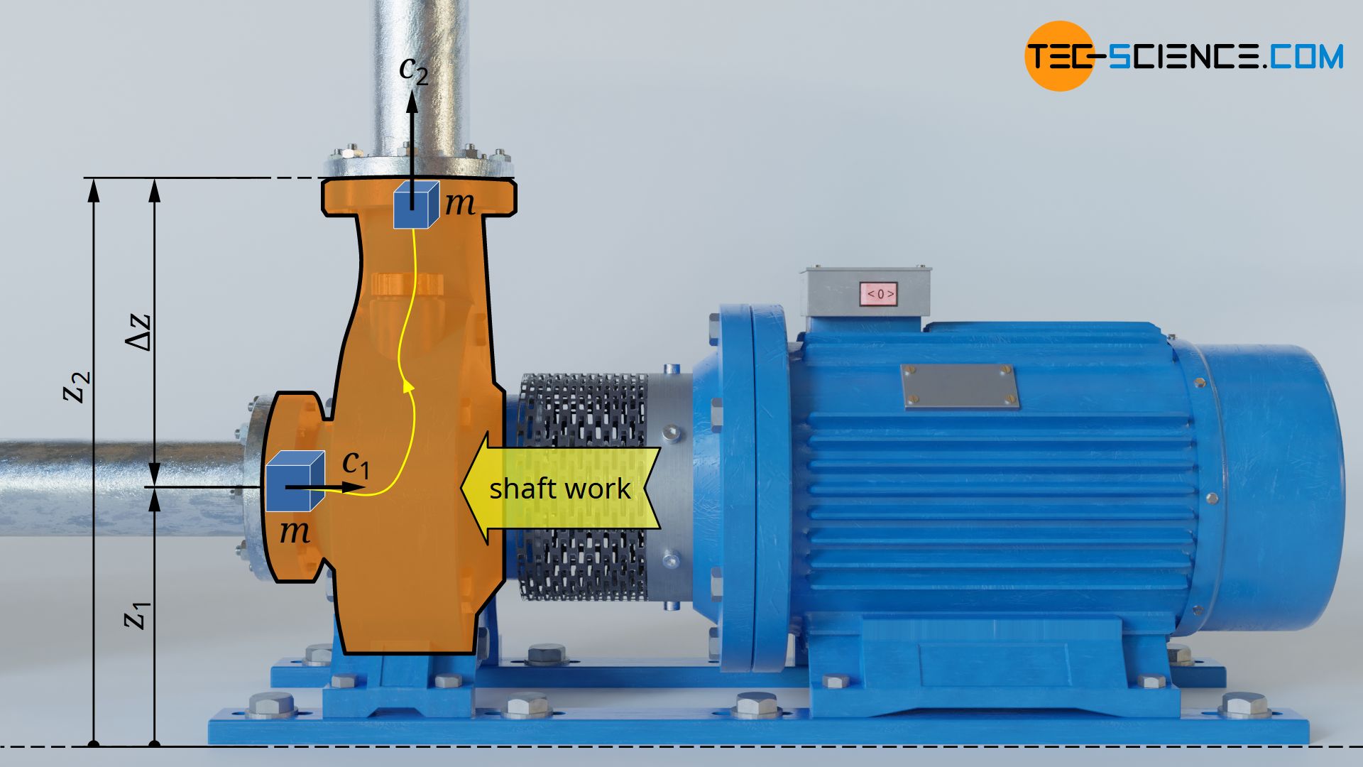
The flow process work Wp in turn can be expressed as the sum of flow work Wf and pressure-volume work Wv. Thus, the shaft work Ws for the frictionless case (Wdiss=0) can also be expressed as follows:
\begin{align}
\label{9318}
&W_\text{s} = \underbrace{W_\text{v} + W_\text{f}}_{W_\text{p}} + W_\text{g} + W_\text{a} \\[5px]
\end{align}
Flowing fluid element as a closed system
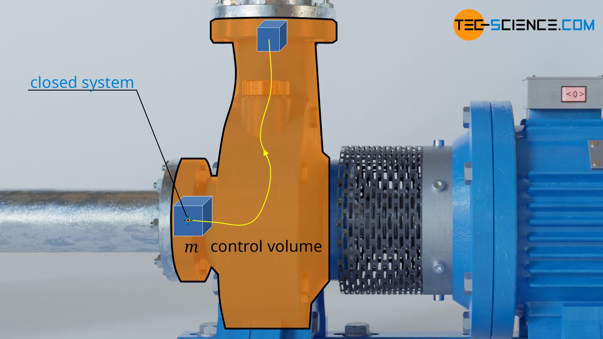
The pressure-volume work Wv in equation (\ref{9318}) is responsible for the fact that the volume of a considered fluid element, which just flows through the open system, changes from V1 to V2. Such a change in volume of a fluid element can be considered to take place in a closed system (see also the article flow process work).
Just imagine a bubble around a fluid volume of mass m with volume V1. This bubble is now sucked in and compressed to the volume V2 (in pumps) or expanded (in turbines). The envelope of the imaginary bubble represents the system boundary across which there is no mass transfer with the surroundings or vice versa. Thus, the volume change of the fluid element in the open system (then also called the control volume) can be considered as taking place in a closed system.
The laws of closed systems can therefore be used as a basis for the calculation of the pressure-volume work, in particular the first law of thermodynamics for a substance in a closed system. This states that for the frictionless case, the supply of pressure-volume work Wv and heat Q leads to a change in the internal energy ΔU of the substance:
\begin{align}
\label{6682}
W_\text{v} + Q = \Delta U \\[5px]
\end{align}
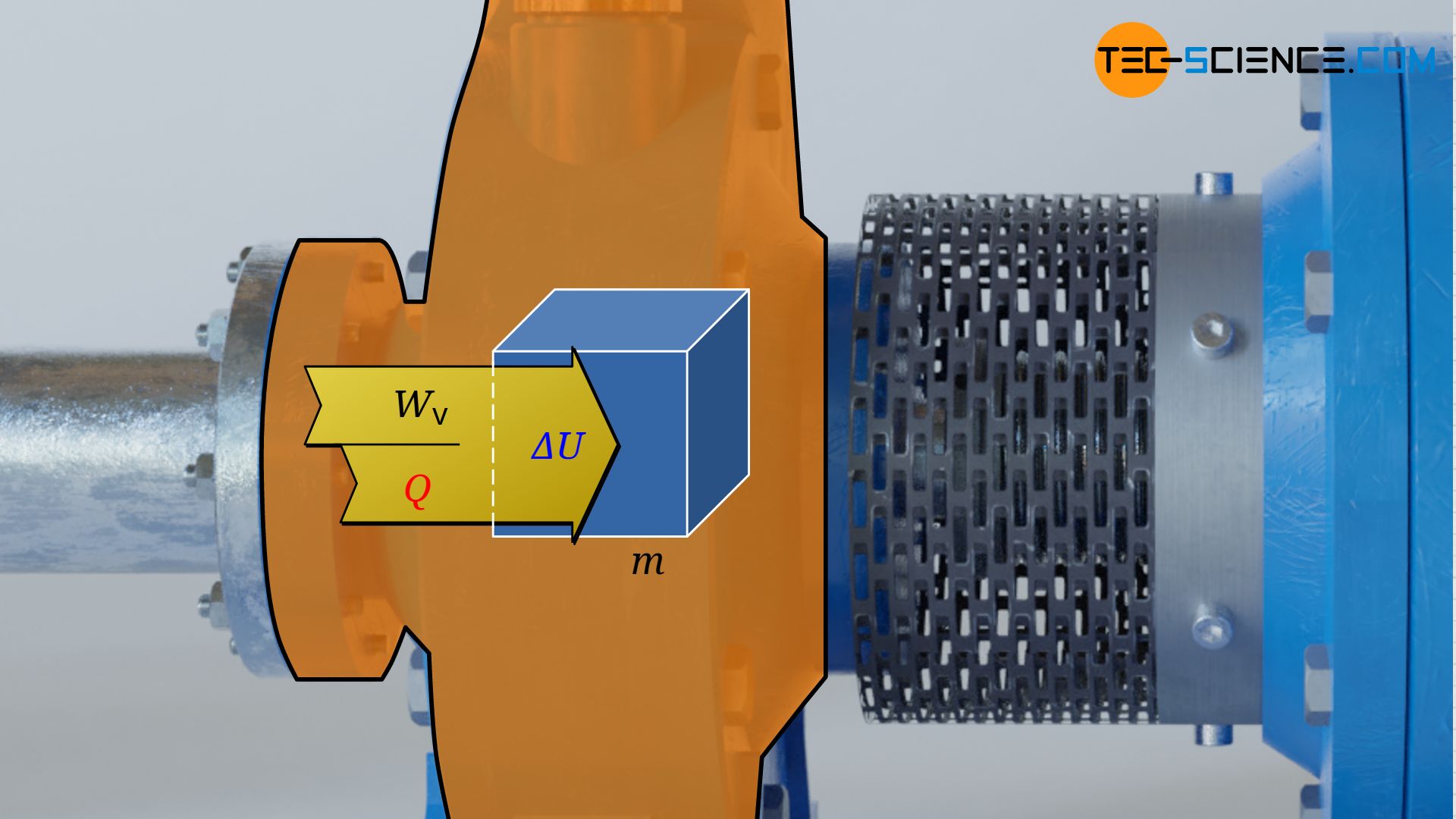
Note: In principle, a change in the kinetic and gravitational energy of the considered fluid element would have to be taken into account for moving closed systems. In the present approach, however, one moves with the center of gravity of the fluid element while it flows through the control volume. Regarding this center of gravity, however, then neither the gravitational energy nor the kinetic energy changes! When viewed from a fixed coordinate system (external observer), the change of gravitational energy and kinetic energy is already accounted for by equation (\ref{9318}) anyway.
Equation (\ref{6682}) explains why the air sometimes has a temperature of over 100 °C when it is pushed out of a compressor. This is because during the compression process, pressure-volume work is done on the gas (Wv>0), which without cooling (Q=0) leads directly to an increase in internal energy (WV=ΔU). Since for ideal gases the internal energy is directly linked to the temperature, the temperature increases. To avoid such, mostly undesirable temperature increases, compressors are usually cooled (Q<0)!
First law of thermodynamics for open systems
The pressure-volume work Wv can thus also be determined according to equation (\ref{6682}) on the basis of the change in internal energy ΔU and the heat transfer Q:
\begin{align}
\label{1957}
W_\text{v} = \Delta U – Q \\[5px]
\end{align}
Equation (\ref{1957}) can now be put into equation (\ref{9318}). Then the terms are sorted according to process quantities and state quantities. Finally, the first law of thermodynamics is obtained for a fluid moving through an open system:
\begin{align}
\label{7962}
&W_\text{s} = \overbrace{\Delta U – Q}^{=W_\text{v}} + W_\text{f} + W_\text{g} + W_\text{a} \\[5px]
\label{6700}
&\underbrace{W_\text{s} + Q}_{\text{process quantities}} = \underbrace{\Delta U + W_\text{f} + W_\text{g} + W_\text{a}}_{\text{changes of state quantities}} \\[5px]
\label{6671}
&\boxed{W_\text{s} + Q = \Delta U + \Delta \left(p~V \right) + m~g~\Delta z + \tfrac{1}{2}~m~\Delta c^2} \\[5px]
&\text{First law for open systems}\\[5px]
\end{align}
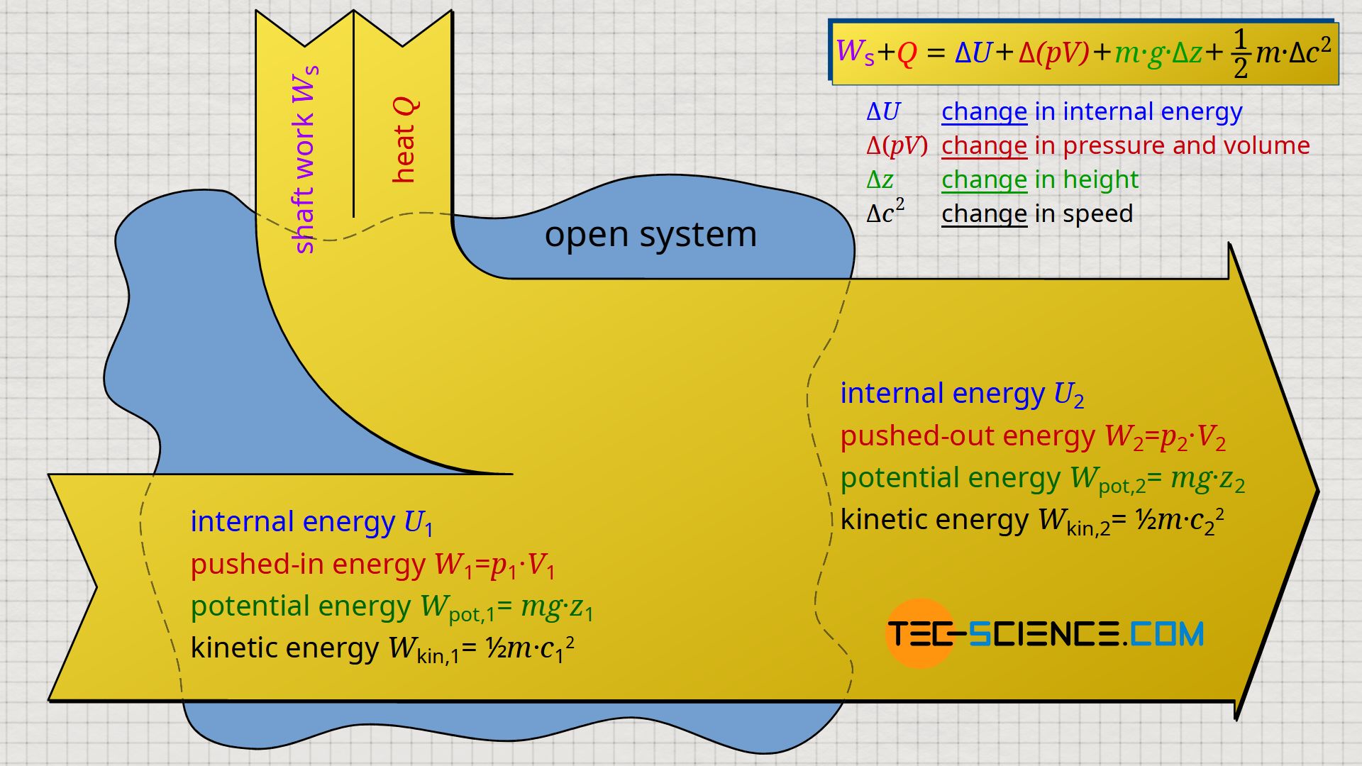
To the left of the equals sign are only process quantities which are transferred to/from the flowing fluid. On the one hand, this is the shaft work Ws, which is usually transferred via shafts, e.g. by the pump shaft or the turbine shaft. On the other hand, heat Q can be transferred, as for example in turbines by the burning of fuel (heat supply) or in the case of compressors by cooling fins (heat dissipation). On the right side of the equals sign, however, there are only state variables which are changed accordingly by this external energy transfer.
Note that the flow work Wf can also be interpreted as a change of state variables. The flow work expresses that a fluid element with initial pressure p1 and volume V1 has been changed to final pressure p2 and volume V2 ⇒ Δ(pV). The flow work is in the thermodynamic sense therefore no process quantity as one could think on the basis of the term work!
The first law can also be stated in specific form (i.e. related to the fluid mass m) and is thus independent of the actual mass flowing through the open system:
\begin{align}
&\boxed{w_\text{s} + q = \Delta u + \Delta \left(p~v \right) + g~\Delta z + \tfrac{1}{2}~\Delta c^2} \\[5px]
\end{align}
Interpretation of the first law of thermodynamics for open systems
Thus, the first law for open systems can be interpreted according to equation (\ref{6671}) as follows: If shaft work Ws and heat Q are transferred across the system boundary to/from a fluid moving through an open system, the fluid will generally undergo the following changes:
- ΔU: the internal energy of the fluid will change. This usually results in a change in temperature.
- Δ(pV): the energy with which the fluid is pushed through the open system due to the acting (static) pressure at the system boundary changes. This is associated with a change in volume and pressure.
- Δz: the gravitational energy of the moving fluid changes, resulting in a change in the position of the center of gravity.
- Δc²: the kinetic energy changes, resulting in altered flow velocities.
In equation (\ref{7962}) the term which accounts for dissipation (Wdiss) was neglected. If dissipation energy is taken into account, the term Wdiss should also appear in equation (\ref{6671}). However, the dissipation energy transferred will sooner or later be dissipated into internal energy anyway, where it will lead to the change in pressure p and volume V . Thus, the dissipation energy is already considered in the terms ΔU and Δ(pV)!
Remark: Equation (\ref{6671}) includes, among other things, the change in internal energy ΔU and the change in pressure and volume Δ(pV). These are typical thermodynamic state quantities. With the concept of enthalpy, these two terms can be combined to form the so-called enthalpy change.
Excursus: Bernoulli equation
The first law of thermodynamics for an open system explained in the previous section can also be applied to pure flow processes of incompressible fluids such as liquids. For this purpose, a frictionless water flow through a pipe with a variable cross-section is considered.
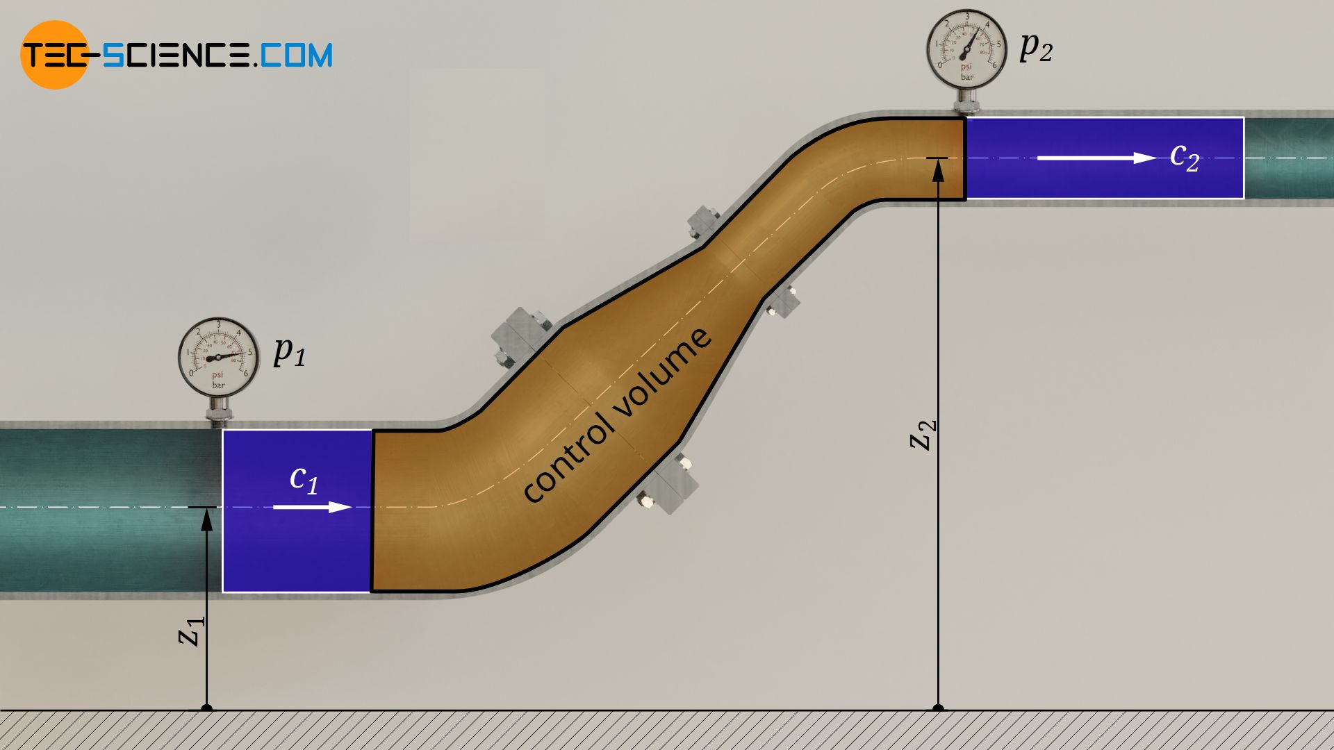
No energy in the form of heat or work is to be transferred to/from the water. The water therefore just flows through the pipe. Thus, both shaft work Ws and heat Q in equation (\ref{6671}) are zero. A change in temperature can therefore also be neglected, so that the internal energy does not change ΔU=0. For this case, the first law then results as follows:
\begin{align}
\label{6570}
\underbrace{W_\text{s}}_{=0} + \underbrace{Q}_{=0} &= \underbrace{\Delta U}_{=0} + \Delta \left(p~V \right) + m~g~\Delta z + \tfrac{1}{2}~m~\Delta c^2 \\[5px]
\label{eq:4700}
0 &= \Delta \left(p~V \right) + m~g~\Delta z + \tfrac{1}{2}~m~\Delta c^2 \\[5px]
\end{align}
If the pressure at the inlet of the pipe is denoted by p1, the volume by V1, the flow velocity by c1 and the inlet height by z1, and the corresponding quantities at the outlet are given the index “2”, the following relationship applies:
\begin{align}
\label{7577}
&0 = \underbrace{p_2~V_2-p_1~V_1}_{\Delta \left(p~V \right)} + \underbrace{m~g~z_2-m~g~z_1}_{m~g~\Delta z} + \underbrace{\tfrac{1}{2}~m~ c_2^2-\tfrac{1}{2}~m~ c_1^2}_{\tfrac{1}{2}~m~\Delta c^2} \\[5px]
\end{align}
Note that for incompressible fluids there is basically no need to distinguish between V1 and V2, since for such cases both volumes are identical. The volume is therefore simply denoted by V (without index). Thus, the following relationship applies between the different quantities at the inlet and outlet:
\begin{align}
\label{8183}
&V~p_1 + m~g~z_1 + \tfrac{1}{2}~m~c_1^2 = V~p_2 + m~g~z_2 + \tfrac{1}{2}~m~c_2^2 \\[5px]
\end{align}
Dividing this equation by the volume V of the considered fluid element yields the so-called Bernoulli equation for inviscid flows of incompressible fluids:
\begin{align}
\label{4404}
&\boxed{p_1 + \rho~g~z_1 + \tfrac{1}{2}~\rho~c_1^2 = p_2 + \rho~g~z_2 + \tfrac{1}{2}~\rho~c_2^2} ~~~\text{Bernoulli equation} \\[5px]
&~~~\text{where: } \rho = \frac{m}{V} \\[5px]
\end{align}


