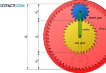
Learn more about the structure and function of the planetary gear in a three-speed gear hub in this article.
Assembly and function
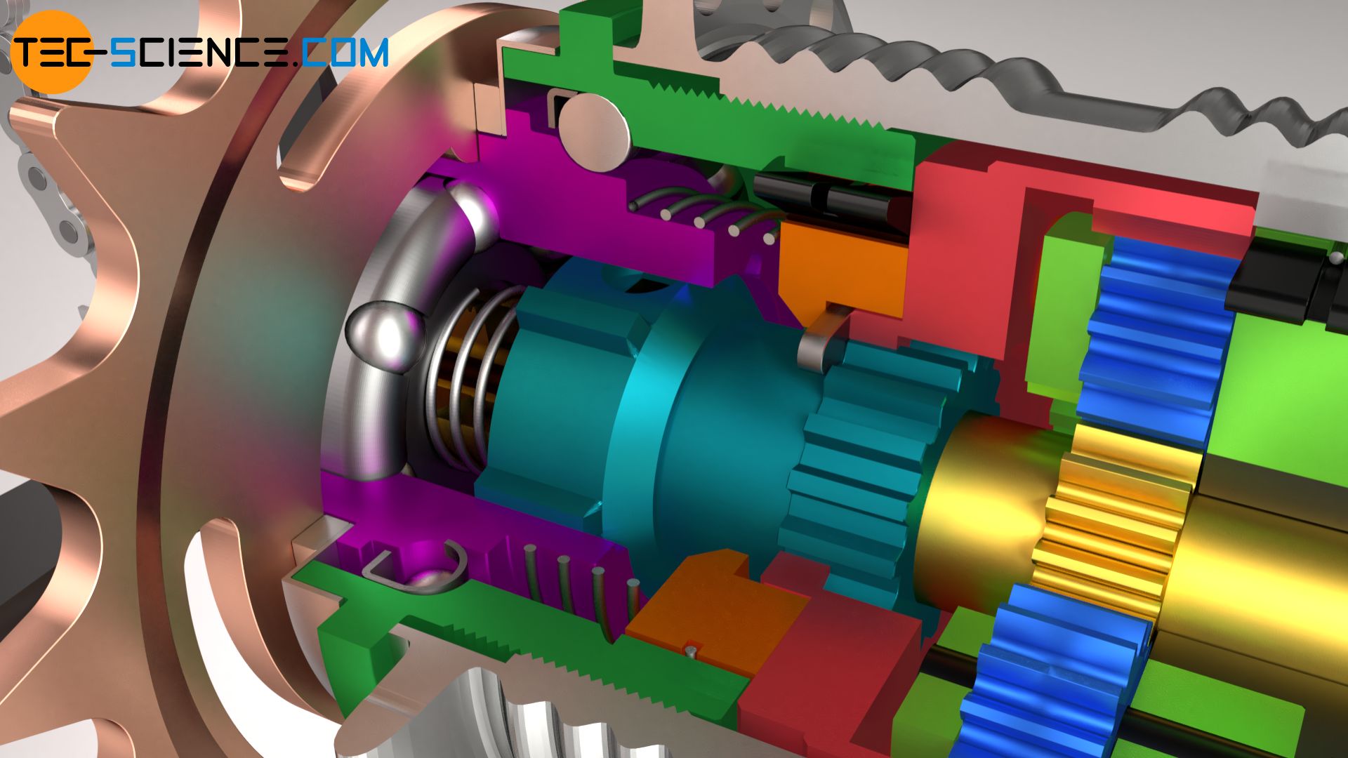
The figure below schematically shows the assembled components of a three-speed gear hub as it can be found in bicycles.
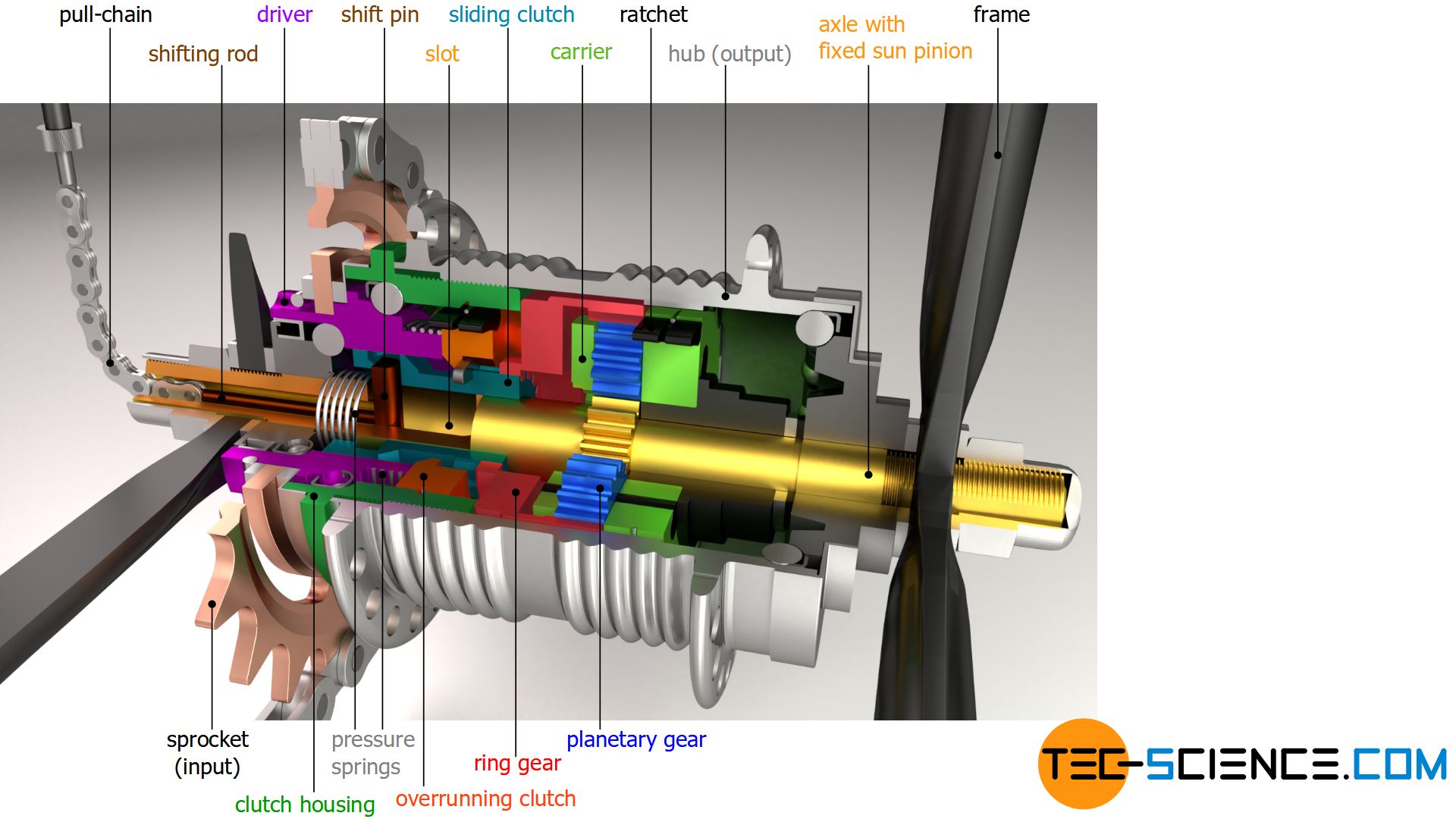
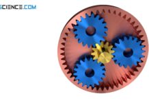
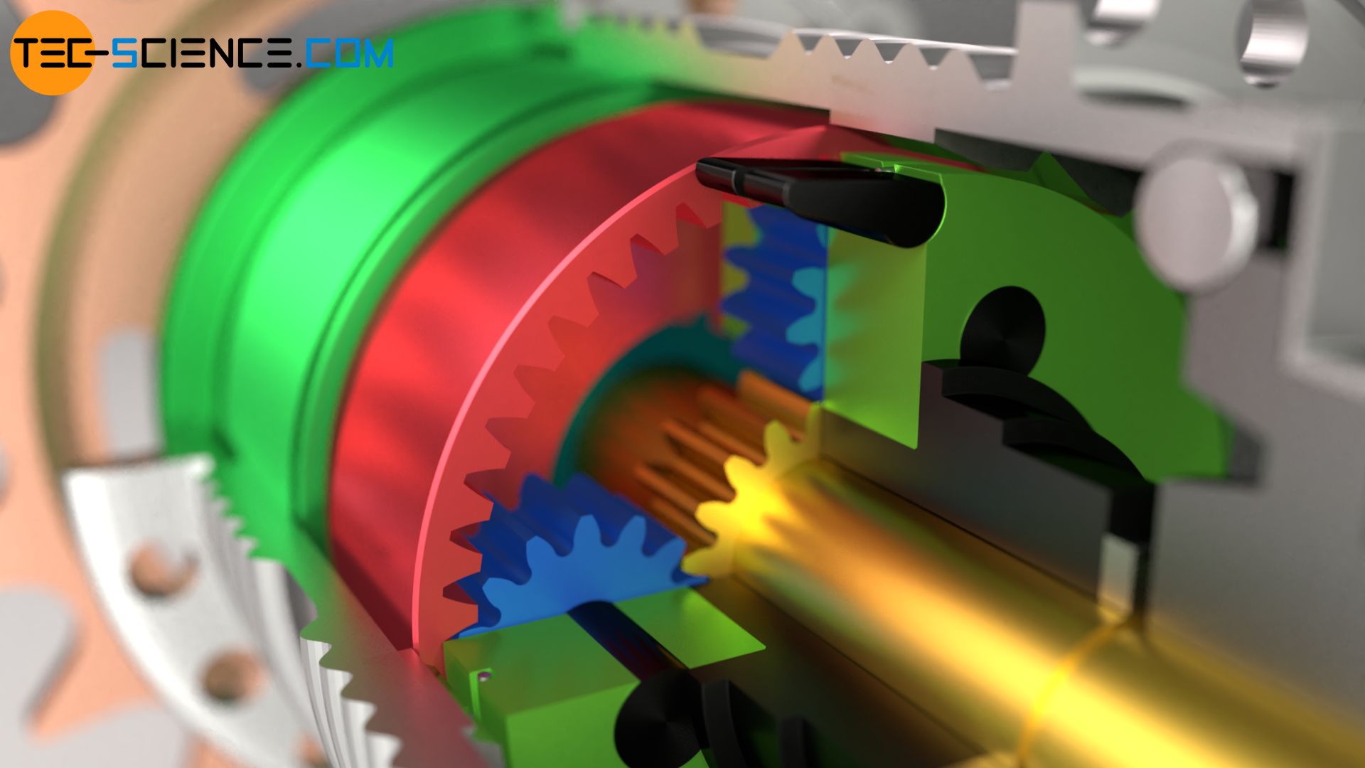
The centerpiece of the gear hub is the planetary gear. The sun gear is fixed to the hub axle, which in turn is connected to the bicycle frame. The hub axle and the sun gear therefore do not perform any rotation during the ride. The planet gears run around the sun gear, which in turn are attached to the carrier and enclosed by the ring gear.
The shift rod is guided through the hollow hub axle and is provided with a shift pin at its end. The shift pin is guided in an elongated hole (slot). Depending on the gear, the shift pin can bring an axially displaceable sliding clutch into different positions by spring force. The position of the sliding clutch is controlled by a pull chain (usually with a wire rope connected) at the end of which the shift lever is located.
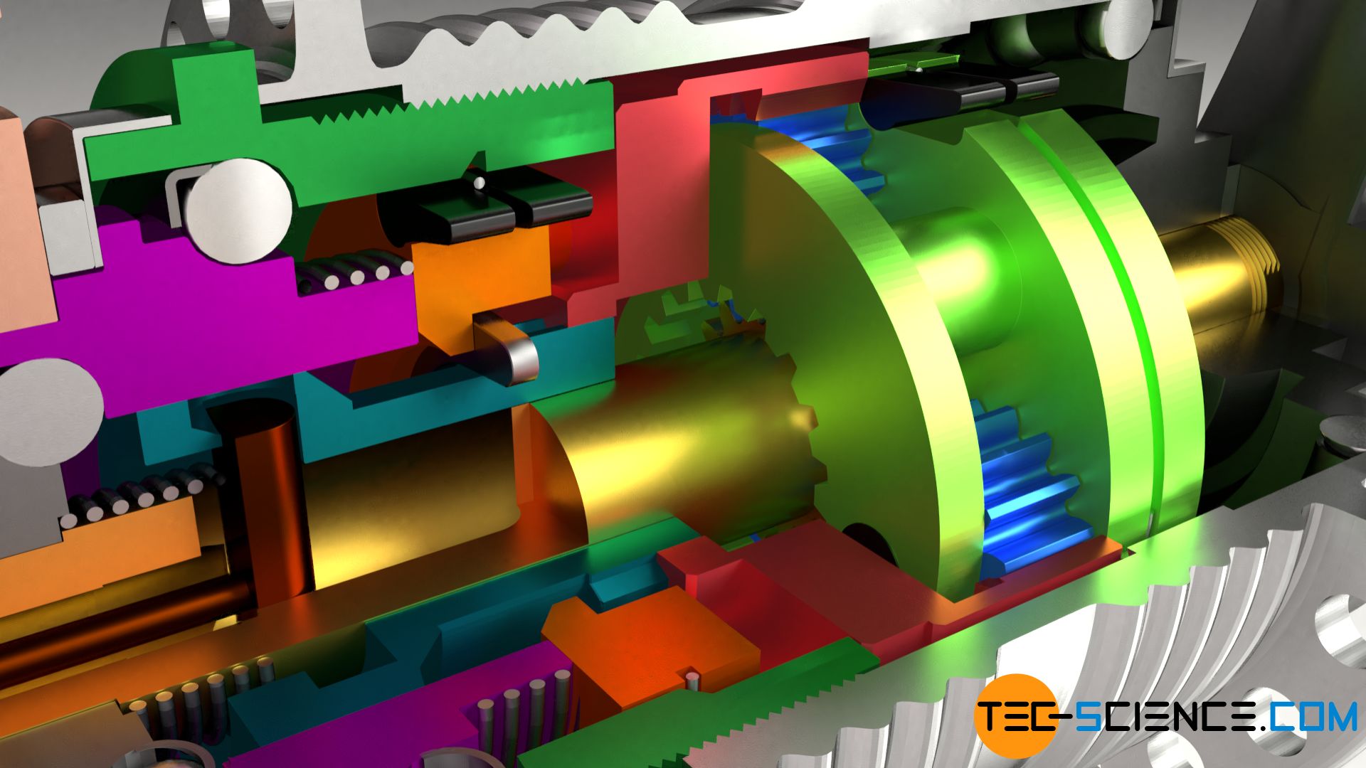
The sprocket is driven by the bicycle chain. It sits on the driver and is firmly connected to it. During rotation, the driver takes the axially displaceable sliding clutch with it in a positive fit.
For power transmission, the sliding clutch is provided with splines (“teeth”) on the circumference, which engage positively in the driver. Depending on the selected gear, the rotation of the sliding clutch is transferred – also by splines – either to the ring gear (1st and 2nd gear) or to the carrier (3rd gear). The different gears are described in more detail in the next section.
Switching of gears
In this section, the shifting of the three speed internal gear hub is explained in more detail. In all gears, the sprocket first drives the driver, which in turn transmits the torque to the sliding clutch. Depending on the position of the sliding clutch, this results in a total of three gears.
1st gear
In the first and second gear, the sliding clutch engages in the ring gear of the planetary gear unit. In the first gear, the ring gear drives the planetary gears around the fixed sun gear. This drives the carrier on which the planet gears are mounted. The ratchets attached to the carrier engage in the recesses of the hub sleeve and thus drive it. The hub rotates and so does the tire attached to it.
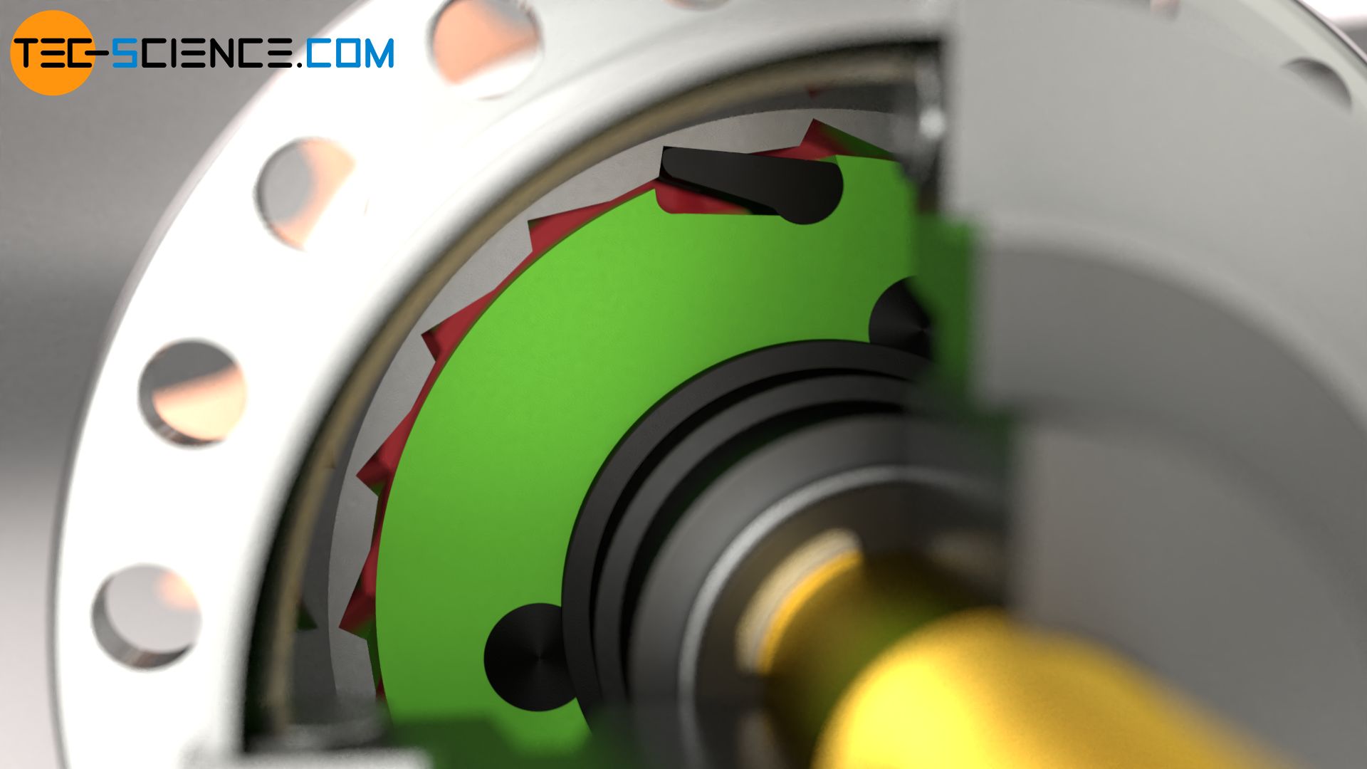
In the first gear, the carrier rotates at a lower speed compared to the ring gear, whereby the ring gear rotates at the frequency of the sprocket. This results in a transmission ratio greater than one. The torque is increased to the same extent as the speed is reduced. This provides a relatively large force on the rear wheel as is usual for a first gear.
2nd gear
To shift to second gear, the shift lever is “loosened” and the shift cable is extended. Both the sliding clutch and the overrunning clutch move forward due to the force of the spring. This also causes the ratchets of the overrunning clutch to now engage in the recesses of the clutch housing (in 1st gear the ratchets are retracted in the clutch housing and are therefore not engaged). The clutch housing is screwed directly into the hub sleeve and thus firmly connected to it.
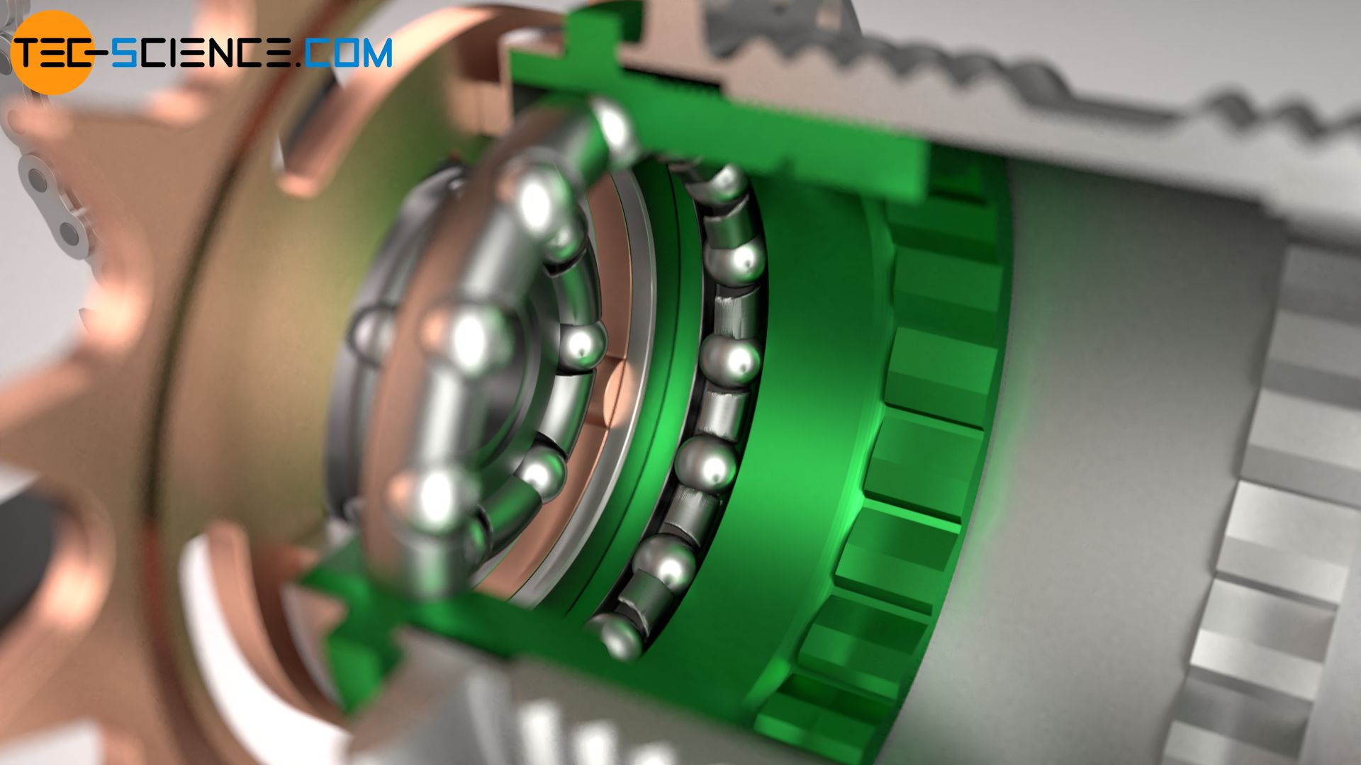
The torque generated by the sprocket is thus transmitted directly to the hub via the driver, sliding clutch and clutch housing. It is basically a “rigid” connection of all power-transmitting components. The speed or torque of the sprocket thus corresponds exactly to the speed or torque of the rear wheel. The planetary gear is thus bypassed and a 1:1 ratio is obtained (direct drive).
Note: Although the carrier is also driven simultaneously by the ring gear, the overrunning clutch of the carrier sets the carrier into a so-called freewheeling mode and thus does not participate in power transmission (for further information see section overrunning clutch).
3rd gear
When shifting into third gear, the shift cable is “loosened” again by switching the gear lever. However, since the overrunning clutch of the ring gear is already at the stop, it cannot disengage any further. Only the slipping clutch pushes further forward and drives out of the ring gear and engages in the carrier.
In this way, the carrier is now driven by the sprocket and drives the planet gears around the fixed sun gear. Accordingly, the ring gear starts to move and rotates at a higher speed than the carrier. Finally one gets a transmission ratio smaller than one.
The higher rotational speed of the ring gear is transmitted to the clutch housing and then to the hub by the overrunning clutch attached with pins. As in second gear, in third gear the bridge, which rotates slower than the hollow gearwheel, is moved back into the freewheel via the overrunning clutch.
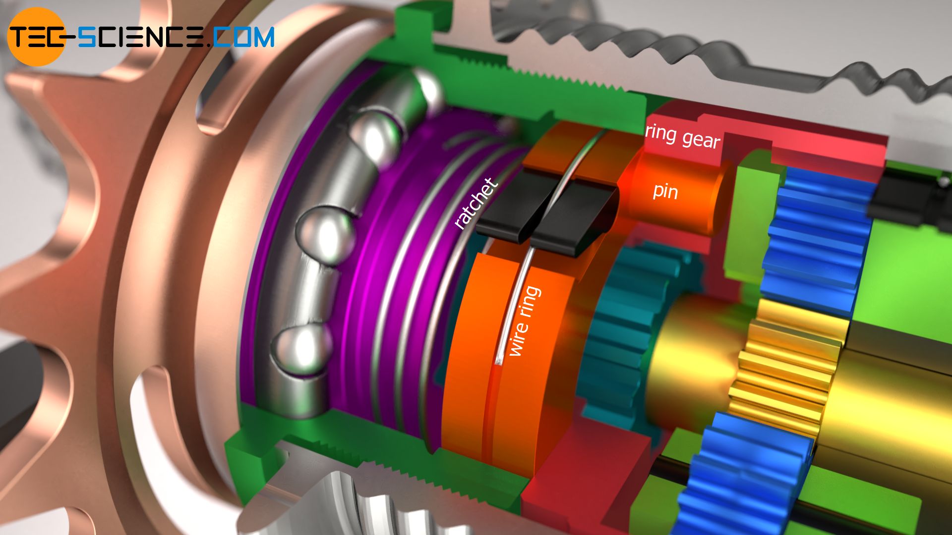
The third gear thus behaves exactly the opposite of the first gear in terms of transmission ratio. In the first gear the carrier is driven by the ring gear and in the third gear the carrier drives the ring gear. Thus the transmission ratios are reciprocal to each other.
Overrunning clutch
The ratchets mentioned in the previous section are part of the so-called overrunning clutch. This overrunning clutch has the task of enabling power transmission in one direction of rotation and locking in the opposite direction, i.e. not enabling power transmission.

The ratchets are simply inserted into the recesses of the overrunning clutch and secured with a wire ring. This wire ring also serves as a kind of “spring”, which is attempted to erect the ratchets. This ensures that the ratchets immediately engage in the provided “ramps” of the clutch housing.
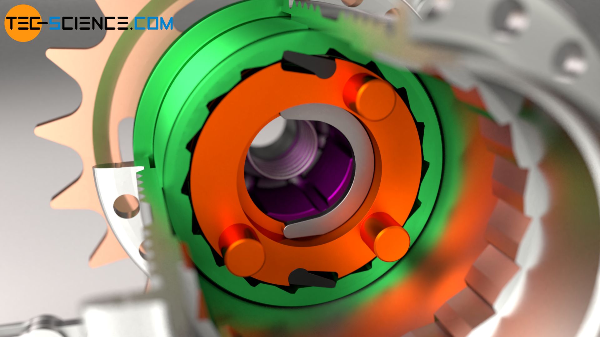
Due to the “ramp shape”, the hub sleeve can also rotate when the sprocket and thus the entire drive train is at a standstill. This has the advantage that the pedals do not have to rotate permanently while driving, but can stand still, e.g. when driving downhill. In the case of such a freewheeling, the ratchets simply slide over the “ramps” of the sawtooth profile. This also explains the typical “ratcheting” noise of stationary pedals and rotating tires. If the rotational speed of the overrunning clutch is increased again, the ratches engage in the clutch housing again by the spring mechanism when the rotational speeds are adjusted.
When freewheeling, the clutch housing can “overrun” the ratchets, so to speak, but not vice versa, which gives this device the name “overrunning clutch” (also known as a locking device or freewheel).
A total of two overrunning clutches are installed in the internal-gear hub. Another one is located directly on the carrier. This is necessary because the carrier of a planetary gear always rotates more slowly than the ring gear. Especially in the second and third gear, the output takes place through the ring gear, which must be able to rotate faster than the carrier. In these cases the carrier must be set into a freewheel (for reasons of clarity the carrier is not shown in the animation below but only its ratchets and the wire ring).


