In the case of a profile shift, the reference profile of the gear is shifted outwards during the manufacturing process in order to positively influence the meshing.
Introduction
In the article Undercut of gears it was shown that avoiding an undercut with a standard gear (standard pressure angle of 20°) requires a minimum number of teeth of 17. If gears are nevertheless to be manufactured below the limit number of teeth (e.g. because a certain transmission ratio is to be achieved), the undercut must be avoided in another way. For this purpose, a so-called profile shift can be used. Such a profile shift is described in more detail in this article.
Profile shift
With a profile shift, the tool profile is shifted outwards by a certain amount during gear cutting. The animation below shows the effects of a profile shift on the tooth form of a gear with 8 teeth. It becomes clear that as the profile shift increases, the undercut becomes smaller and can even be completely avoided.
The figure below shows again the comparison of the tooth shapes with increasing profile shift (from left to right). Even if the tooth shapes differ from each other, the teeth can still mesh with each other. Profile shifted gears (also called corrected gears) can therefore be easily paired with non-profile shifted gears (so-called standard gears) as long as they are manufactured with the same tool and therefore have the same module.
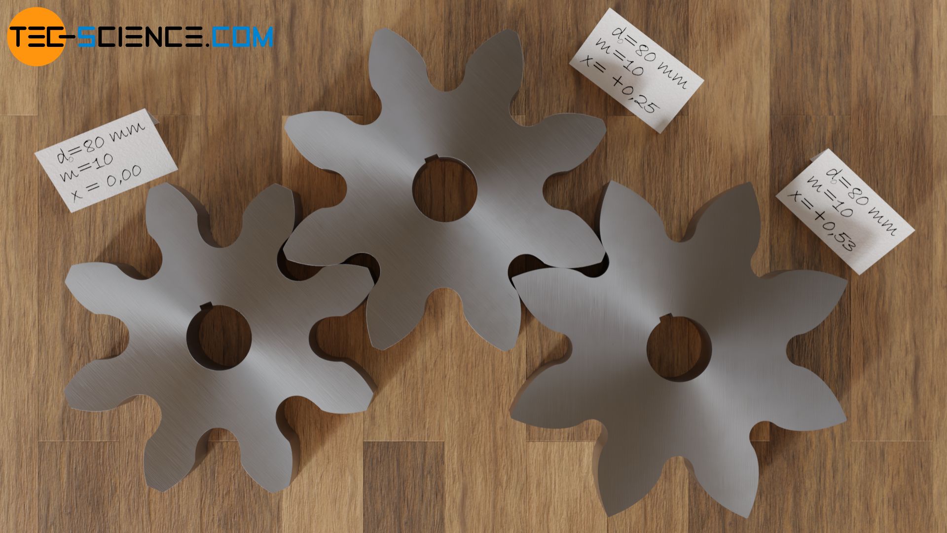
Undercuts can be avoided with a profile shift. For this purpose, the tool profile is shifted outwards during gear manufacturing. Gears with different profile shifts can mesh with each other without further ado!
Influence of the profile shift on the shape of the tooth flank
Even if this may not seem so at first glance, a profile shift has no influence on the shape of the tooth flank itself. All profile shifted gears use the same involute for the tooth shape compared to their corresponding standard gears. Only another part of the same involute is used. This becomes clear when the tooth flanks of the gears with different profile shifts are placed on top of each other.
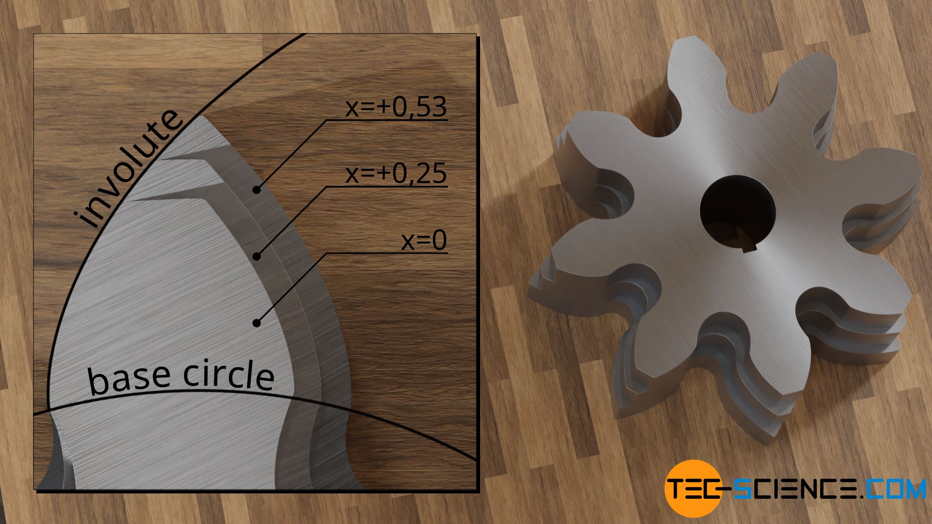
Note that the base circle for constructing the involute is determined solely by the flank angle of the tool profile (= standard pressure angle) during gear cutting. And since the angle of the cutting edges does not change with a profile shift, the base circle and thus the involute do not change either.
For profile-shifted gears, the same involute is used for the shape of the tooth flank. The base circle therefore does not change with a profile shift, since the base circle is determined solely by the flank angle of the cutting tool (standard pressure angle)!
As already explained in the article Construction and design of involute gears, the radius of curvature of the involute increases with increasing length, i.e. the further away the involute is from the base circle, the larger the radius of curvature is and the less strongly it is therefore curved. The flank shape at this more distant area is rather “flat” than “pointed”. The smaller curvature leads to a larger contact surface of the flanks, which reduces the pressure accordingly (less Hertzian contact stress). This reduces the stress on the flanks and thus increases the flank load-bearing capacity.
The flank load-bearing capacity can be increased by a profile shift!
Influence of a profile shift on the standard reference pitch circle
The reason why profile-shifted gears can engage with other profile-shifted gears is that all gears have the same circular pitch on their manufacturing pitch circles. This will be explained in more detail in this section.
First of all, it should be noted that the pitch point C between the rack-shaped cutting tool and the gear does not change during gear cutting, even if the profile is shifted (see article rack for further information on this). This is due to the fact that the pitch point is defined as the intersection between the center line and the line of action. The line of action in turn always results as a normal to the tool flank, which is tangent to the base circle of the gear.
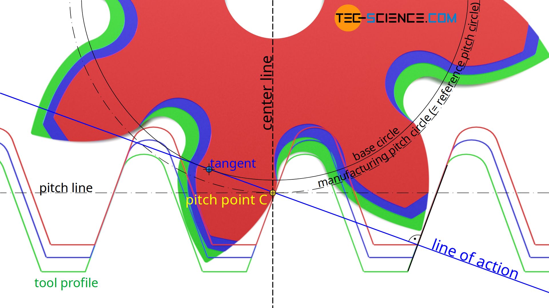
As the figure above shows, a profile shift has no effect on the flank angle of the tool or on the base circle of the gear as mentioned in the previous section. Thus, even with a profile shift, the line of action and thus the pitch point always remain unchanged.
The unchangeable position of the pitch point is already apparent from its meaning. The pitch point describes the point in which the speeds of the rack-shaped tool profile and the gear are identical (“sliding-free rolling”). A radial shift of the tool profile, however, does not change the speed ratios and thus the position of the pitch point.
The pitch line of the tool and the (manufacturing) pitch circle of the gear run through the pitch point. Regardless of the profile shift, the unchangeable pitch point therefore always leads to the same manufacturing pitch circles on the gears. Finally, the pitch of the teeth is referenced to these manufacturing pitch circles (circular pitch p0). This means that the manufacturing pitch circle corresponds to the standard reference pitch circle of the gear (see also the article on racks). A profile shift therefore has no effect on the resulting reference pitch circle and the related circumferential pitch, so that profile-shifted gears can mesh with non-profile-shifted gears!
The reference pitch circle (manufacturing pitch circle) of a gear does not change with a profile shift, so that corrected gears can mesh with standard gears!
Profile shift coefficient
The profile shift V for gears is usually indicated by a profile shift coefficient x in relation to the module m. With positive coefficients (x>0) the tool profile is shifted outwards and with negative factors (x<0) it is shifted inwards (applies to external gears).
\begin{align}
&\boxed{V = x \cdot m} \\[5px]
\end{align}
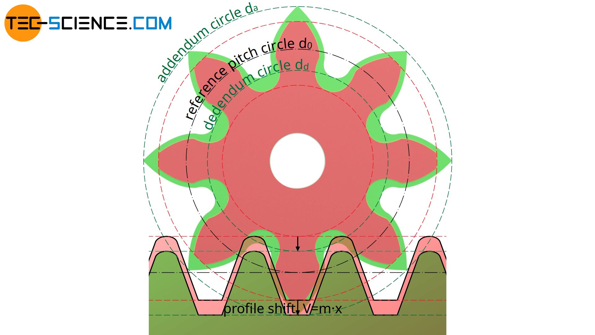
For example, a profile shift coefficient of x=+0.25 means that the tool profile is shifted outwards by 0.25 times the module m. In general, both the root circle radius (dedendum circle) and the tip circle radius (addendum circle) increase by the amount of the profile shift.
The calculation of the root diameter dd,0 and the tip diameter da,0 for standard gears has already been explained in the article Construction and design of involute gears. These diameters result from the module m and the number of teeth z, whereby a clearance c is also taken into account for the root diameter:
\begin{align}
d_{a,0} &= m \cdot (z+2) ~~~&&\text{applies only to standard gears}\\[5px]
d_{d,0} &= m \cdot (z-2) – 2 \cdot c ~~~&&\text{applies only to standard gears}\\[5px]
\end{align}
In case with a profile shift, however, the tip circle radii and the root circle radii are increased by the amount of the (positive) profile shift V with corrected gears. For the corresponding diameters applies:
\begin{align}
&d_a = d_{a,0} + 2 \cdot V = m \cdot (z+2) + 2 \cdot V = m \cdot (z+2) + 2 \cdot m \cdot x \\[5px]
\label{a}
&\boxed{d_a = m \cdot (z+2x+2)} ~~~\text{applies in general (without tip shortening)}\\[5px]
&d_d = d_{d,0} + 2 \cdot V = m \cdot (z-2) – 2 \cdot c + 2 \cdot V = m \cdot (z-2) – 2 \cdot c + 2 \cdot m \cdot x \\[5px]
&\boxed{d_d = m \cdot (z+2x-2) -2c } ~~~\text{applies in general}\\[5px]
\end{align}
Increase of tooth thickness
A profile shift also has an effect on the circular tooth thickness and the tooth space width. As the tooth thickness s0 increases on the pitch circle, the tooth space e0 decreases accordingly. In the following, the tooth thickness s0 on the reference pitch circle is determined as a function of the profile shift coefficient x.
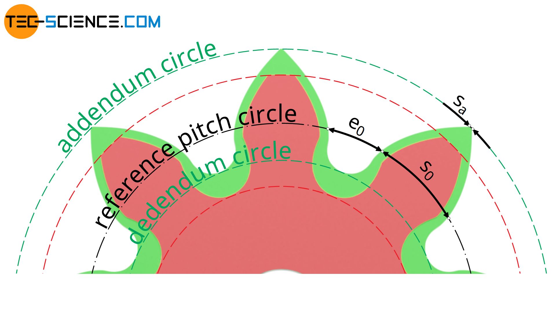
The figure below shows the increase in the distance of the tool flanks on the pitch line (width Δs of the triangle marked blue) when the tool profile is shifted outwards by the profile shift V=x⋅m. This distance of the tool flanks on the pitch line corresponds to the tooth thickness s0 on the manufacturing pitch circle of the gear (= reference pitch circle).
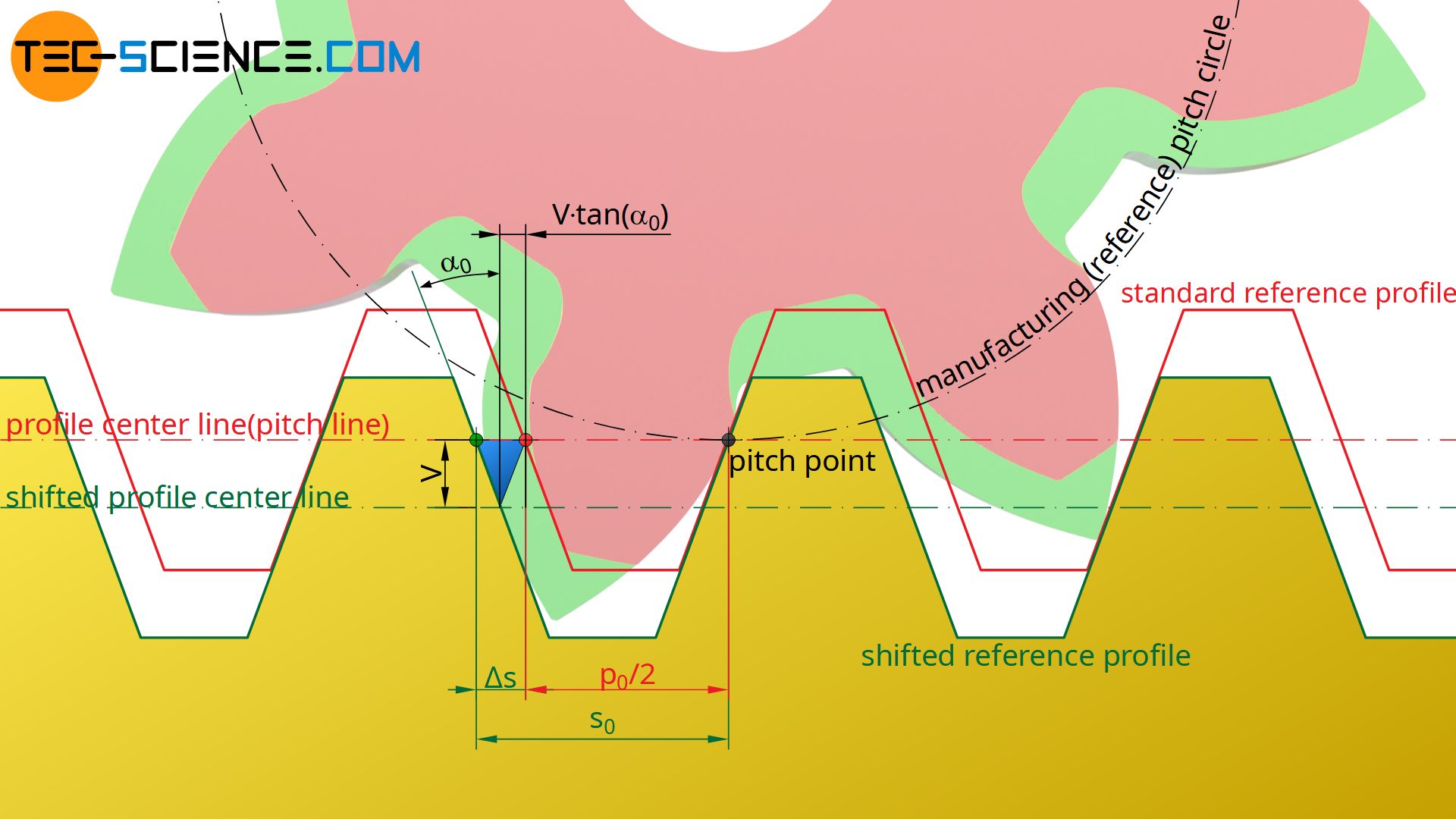
In comparison to a standard gear, whose tooth thickness corresponds to half the circular pitch p0 (p0/2), with a corrected gear the tooth thickness increases by an amount Δs. The figure above shows the following relationship between the profile shift coefficient x and the resulting tooth thickness s0 on the pitch circle (with α0 as the standard pressure angle):
\begin{align}
&s_0 = \frac{p_0}{2} + \Delta s \\[5px]
&s_0 = \frac{p_0}{2} + 2 \cdot V \cdot \tan(\alpha_0) \\[5px]
&\underline{s_0 = \frac{p_0}{2} + 2 \cdot m \cdot x \cdot \tan(\alpha_0)} \\[5px]
\end{align}
The circular pitch p0 can also be expressed by the module m (see article Construction and geometry of involute gears):
\begin{align}
&\underline{p_0 = \pi \cdot m} \\[5px]
\end{align}
Finally, for the tooth thickness s0 on the reference pitch circle of a profile shifted gear applies:
\begin{align}
&s_0 = \frac{\pi \cdot m}{2} + 2 \cdot m \cdot x \cdot \tan(\alpha_0) \\[5px]
&\boxed{s_0 = m \cdot \left(\frac{\pi}{2} +2 \cdot x \cdot \tan(\alpha_0) \right) } ~~~\text{with } \alpha_0 = 20° \\[5px]
\end{align}
By the same amount Δs as the tooth thickness increases, the tooth space width e0 decreases:
\begin{align}
&\boxed{e_0 = m \cdot \left(\frac{\pi}{2} – 2 \cdot x \cdot \tan(\alpha_0) \right) } \\[5px]
\end{align}
Tip shortening
In the previous section it was shown that a (positive) profile shift increases the tooth thickness on the reference pitch circle and thus increases tooth strength. At the same time, however, the width of the tooth tip sa on the addendum circle is reduced.
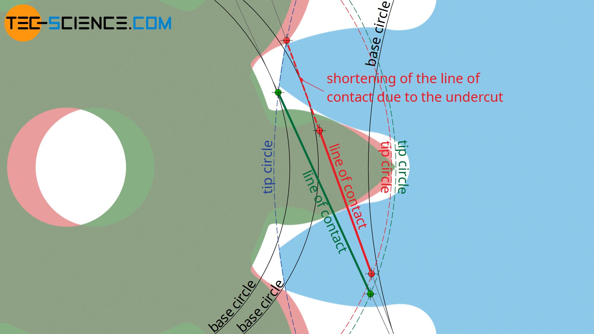
If the tip of the tooth is too small, however, there is a risk of teeth breaking out. In order to prevent this, the tip diameter must then be shortened so that a certain thickness is maintained. The tip diameter should be shortened in such a way that the tooth thickness at the addendum circle is at least 0.2 times the module (such a tip shortening shortening is not yet considered in the equation (\ref{a})!). Note that with a shortend tip diameter the line of contact is reduced accordingly! The detailed calculations for determining the line of contact are shown in the article Calculation Of Involute Gears.
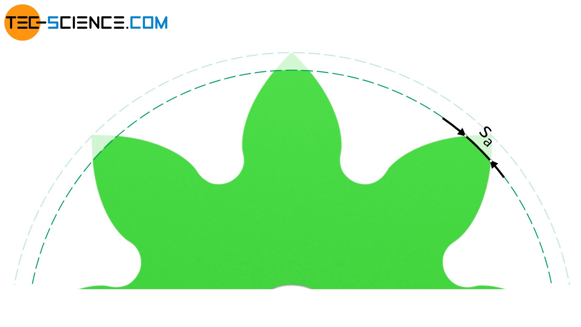
The thickness of the tip tooth at the addendum circle should be at least 20 % of the module. To achieve this, a tip shortening may be necessary! This reduces the line of contact!
The animation below shows the profile shift of a gear with 6 teeth to avoid an undercut. In this case, the thickness of the tip tooth even decreases so much that the involutes taper before the shifted tip diameter is reached. The increase of the tip circle radius by the amount of the profile shift cannot therefore be maintained in this case – the tip diameter is inevitably shortened.
In addition, the tip circle would have to be shortened again to at least 0.2 times the module in order to increase the thickness of the tip tooth. However, such a large reduction of the tip circle would also result in a correspondingly large reduction of the line of action. Involute gears with fewer than 7 teeth should therefore be avoided by any means.
Involute gears with less than 7 teeth should be avoided due to excessive tip shortening!
Center distance and operating pressure angle
In the previous section it was shown that with corrected gears (green gear in the figure below) an extended part of the involute is used as tooth flank compared to standard gears (shown in red). When meshing with another gear, this further curved part of the involute is used for power transmission. Therefore, there is a clearance between the tooth flanks when the center distance a is increased by the amount of the (positive) profile shift V=x⋅m. The back flank bends away before it touches the flank of the other gear, so to speak.

For a backlash-free engaging, the gears must therefore be moved together a little bit. This reduces the centre distance slightly, but it is still larger compared to the a standard gear. At the same time, however, the clearance c between the tip of the tooth and the tooth root of the other gear is reduced (see figure below). This may require a tip shortening in order to maintain a certain clearance.

The center distance is therefore larger with a positive profile shift and smaller with a negative profile shift compared to standard gears without a profile shift. This means that the center distance can be adjusted by means of a profile shift. This is another reason why a profile shift is frequently used.
Profile shifts are often used to adjust the centre distance!
In addition to the effects already mentioned, a profile shift also results in a change in the operating pressure angle α. The operating pressure angle α is not to be confused with the standard pressure angle α0, which ultimately determines the flank angle of the rack-shaped cutting tool and of course does not change with a profile shift!
Detailed calculations for determining the operating pressure angle and the centre distance are shown in the article Calculation of involute gears.
Calculation of the profile shift coefficient to avoid undercutting
In the article Undercut it was shown that below the minimum number of zmin=17 teeth an undercut occurs which weakens the teeth. A profile shift now provides the possibility to completely compensate such an undercut. This raises the question of how the profile shift coefficient x must be chosen to avoid an undercut with a given number of teeth z<zmin.
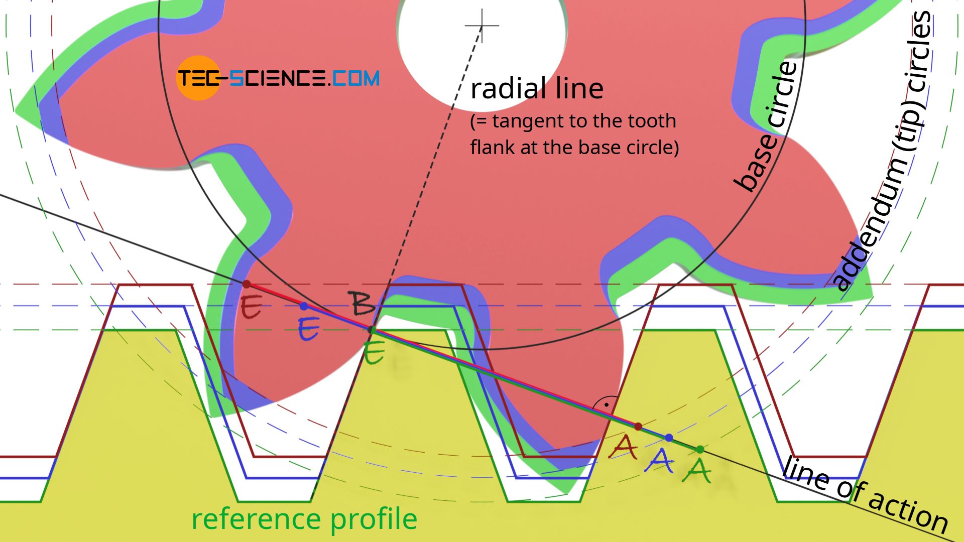
As also explained in detail in the article Undercut, in order to avoid an undercut, the intersection point B between the base circle and the line of action must be located outside the line of contact AE. In the limiting case where an undercut is to be avoided, the beginning of the undercut coincides with the end of the line of action. Then the reference profile (“tool profile”) exits the gear before it undercuts the tooth.
As the animation above shows, the displacement of the tangent point B to the end of the line of contact in point E is achieved by a positive profile shift. Note that the end of contact is determined by the intersection of the line of action and the tip line of the reference profile and can therefore be influenced by a profile shift, whereas the line of action does not change if the profile is shifted!
In the limiting case, the tangent point B coincides with the end of engagement E, as it is the case for the green gear. From the resulting geometrics, the profile shift coefficient x can be determined for a given standard pressure angle α0.
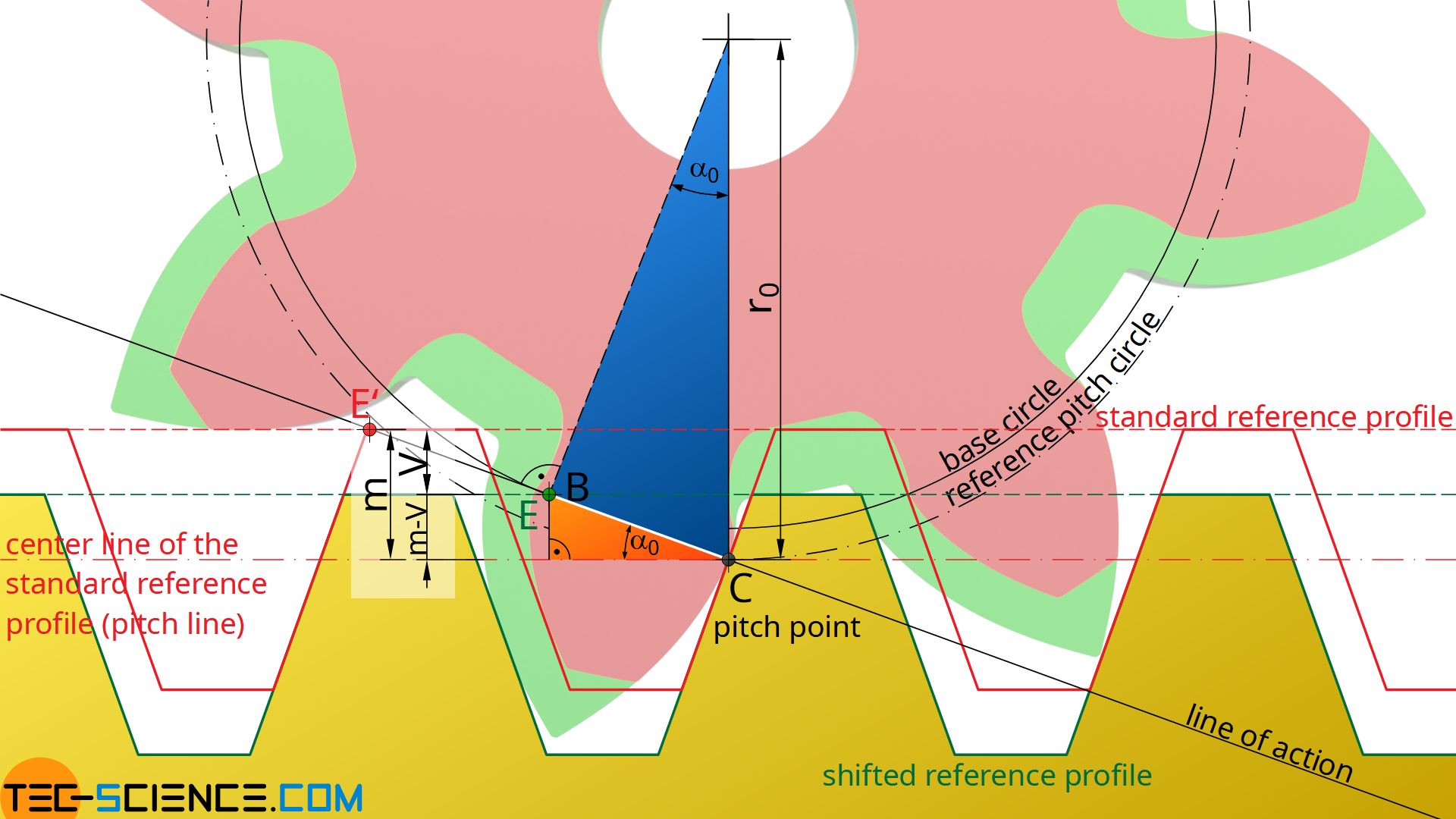
The orange triangle in the figure above is now considered more closely. It is shown that the opposite side of the standard pressure angle α0 corresponds to the difference between the module m and the profile shift V=x⋅m. Therefore, the following relationship applies to the distance CE between the pitch point C and the end of engagement E:
\begin{align}
&\sin(\alpha_0) = \frac{m-V}{\overline{CE}}= \frac{m-m \cdot x}{\overline{CE}} = \frac{m\cdot (1-x)}{\overline{CE}} \\[5px]
\label{1}
&\underline{\overline{CE} = \frac{m \cdot (1-x)}{\sin(\alpha_0)}} \\[5px]
\end{align}
Now the blue triangle is considered more closely. It is shown that the distance CE can also be determined from the pitch circle radius r0 or the pitch circle diameter d0. The pitch circle diameter results from the module m and the number of teeth z.
\begin{align}
&\overline{CE} = r_0 \cdot \sin(\alpha_0) = \frac{d_0}{2} \cdot \sin(\alpha_0) = \frac{m \cdot z }{2} \cdot \sin(\alpha_0) \\[5px]
\label{2}
&\underline{\overline{CE} = \frac{m \cdot z}{2} \cdot \sin(\alpha_0)} \\[5px]
\end{align}
The two equations (\ref{1}) and (\ref{2}) can now be equated and solved for the profile shift coefficient x:
\begin{align}
&\overline{CE} = \overline{CE} \\[5px]
&\frac{m \cdot (1-x)}{\sin(\alpha_0)} = \frac{m \cdot z}{2} \cdot \sin(\alpha_0) \\[5px]
&\underline{x = 1-z \cdot \frac{\sin^2(\alpha_0)}{2} } \\[5px]
\end{align}
Furthermore, the term sin²(α0)/2 in the equation above corresponds to the reciprocal of the minimum number of teeth zmin, above which an undercut would occur without a profile shift (for the derivation of the formula, see article Undercut). For a gear with a standard pressure angle of α0=20°, the minimum number of teeth is theoretically zmin=17. The profile shift coefficient x required to avoid an undercut can thus be determined as follows:
\begin{align}
&\boxed{x = 1-\frac{z}{z_{min}} } ~~~ \text{with } z_{min}=17 \\[5px]
\end{align}
For a gear with z = 8 teeth, the profile shift coefficient is x=0.53. In practice, a slight undercut can often be accepted without major negative effects. In these cases the minimum number of teeth is assumed to be zmin=14.
Note that for a number of teeth greater than zmin, the profile shift coefficient x becomes negative. This means that theoretically a negative profile shift can be made without undercutting.
Summary
In summary, it can be stated that a (positive) profile shift is always applied if …
- an undercut is be avoided,
- the tooth strength must be increased,
- the surface pressure at the flanks is to be decreased, or
- the center distance must be adjusted.
With external gears, a positive profile shift leads to …
- an increase of the root circle,
- an increase of the tip circle,
- an increase of the tooth root thickness (increased strength) and thus to
- a reduction of the undercut,
- a decrease of the tip tooth thickness (tip shortening may be necessary),
- an increase of the tooth thickness at the pitch circle and to
- a decrease of the tooth space width at the pitch circle,
- a decrease of the Hertzian contact stress on the flanks (increased flank load-bearing capacity) and to
- an increase of the centre distance when meshing with a standard gear.
Neither the base circle diameter nor the reference pitch circle diameter change with a profile shift! In the case of a negative profile shift, the effects listed above are just the opposite. Due to the many positive effects, a profile shift is generally recommended.


")

")
