Learn in this article how to calculate the length of belts for belt drives.
For the construction of belt drives it is necessary to determine both the wrap angle and the belt length for given pulley diameters and pulley spacings. The basis for this is the mounted condition of the belt on the pulleys.
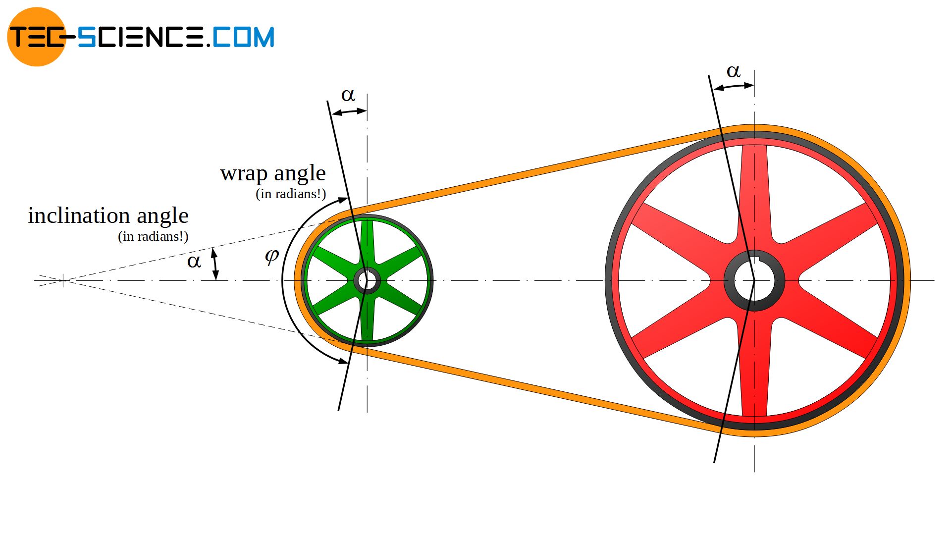
The belt is then composed of the two arc-shaped sections bs and bl on the small and large pulley and of the two straight belt sections l. The sum of these belt sections forms the geometric belt length Li in the mounted state, whereby this length specification then refers to the inner surface of the belt:
\begin{align}
\label{riemenabschnitte}
&L_i = 2 \cdot l + b_l + b_s \\[5px]
\end{align}
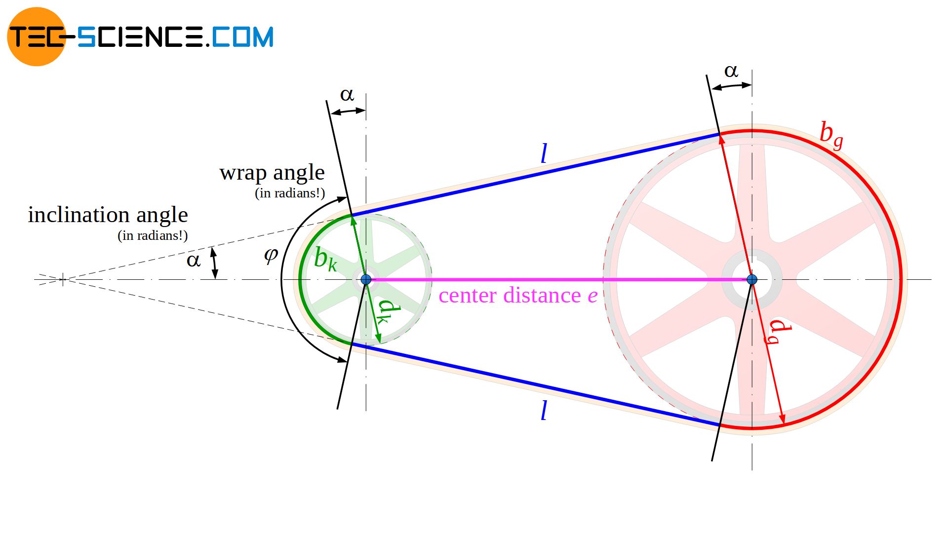
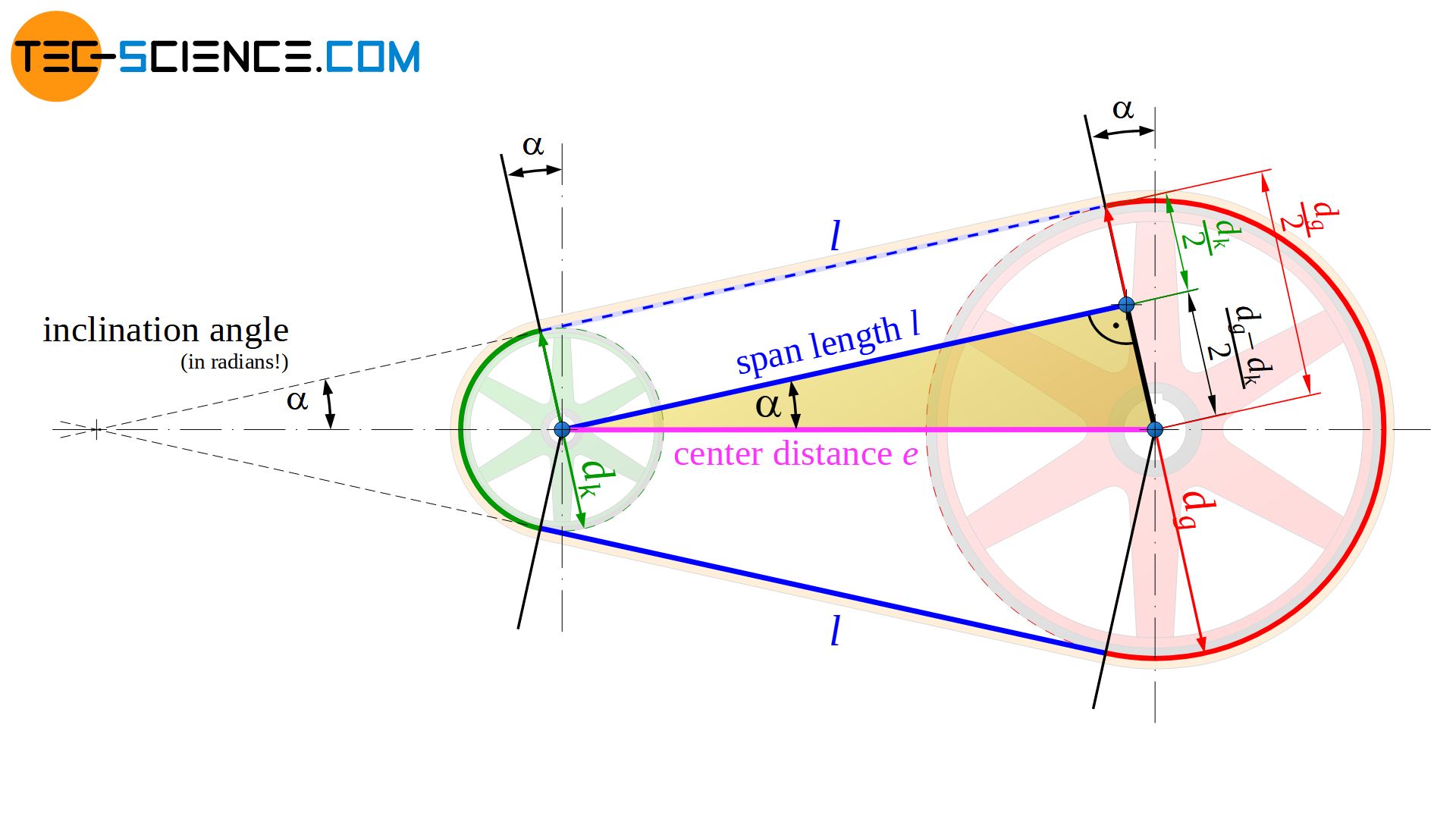
First, the wrap angle is to be determined on the basis of the pulley diameter and the distance between the pulleys. The angle of inclination \(\alpha\) is used for the derivation, which results as the angle between the center line of the pulleys and the straight line of the belt. As the figure above shows, the inclination and the wrap angle φ of the small pulley are related as follows (unless explicitly stated otherwise, the entire angle specifications and functions refer to the radians!):
\begin{align}
\label{a_p}
&\boxed{\varphi = \pi – 2 \cdot \alpha} \\[5px]
\end{align}
Now move the straight belt section l along the angular auxiliary lines to the center of the small pulley. This results in a right-angled triangle with the center distance e as hypotenuse and the span length l as ankathete, as well as the opposite cathete resulting from the pulley diameters. The angle of inclination \(\alpha\) can then obviously be determined from the sinus function by the pulley diameters and the center distance:
\begin{align}
&\sin(\alpha) =\frac{d_l-d_s}{2e} \\[5px]
\label{trumneigung}
&\boxed{\alpha =\arcsin\left(\frac{d_l-d_s}{2e}\right)} \\[5px]
\end{align}
In combination with equation (\ref{a_p}) the wrap angle φ can finally be calculated as follows by the pulley diameters dl and ds and the center distance e:
\begin{align}
\label{phi}
&\boxed{\varphi = \pi – 2 \cdot \arcsin\left( \frac{d_l-d_s}{2e}\right)} ~~~\text{ radian measure!} \\[5px]
\end{align}
For the derivation of the belt length, the resulting triangle in the figure above can also be used. Thus, the span length l can be determined as a function of the center distance e by the cosine function of the inclination angle \(\alpha\):
\begin{align}
\label{trumlaenge}
&\underline{l = e \cdot \cos(\alpha) } \\[5px]
\end{align}
To determine the belt section around the large pulley bl, first determine the length of the corresponding semicircle (π/2⋅dl). However, the two arc sections (dl/2⋅\(\alpha\)) must also be added, which result from the inclination with the angle \(\alpha\) (Note: arc angle equals arc length divided by arc radius or arc length equals arc radius times arc angle):
\begin{align}
\label{b_g}
&\underline{b_l =\tfrac{\pi}{2}d_l+2 \cdot \tfrac{d_l}{2}\cdot \alpha} \\[5px]
\end{align}
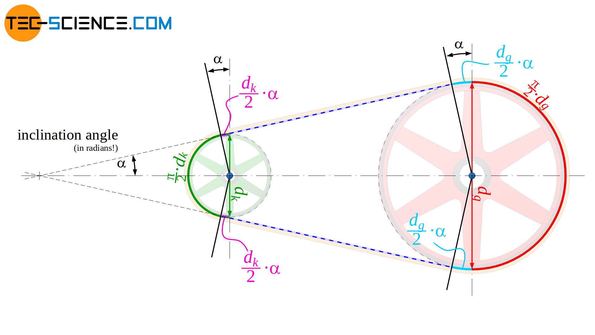
The arc length of the belt around the small pulley bs is determined in the analog way. Starting from the semicircle length π/2⋅ds, however, the two arc lengths ds/2⋅\(\alpha\) must now be subtracted due to the inclination:
\begin{align}
\label{b_k}
&\underline{b_s =\tfrac{\pi}{2}d_s-2 \cdot \tfrac{d_s}{2}\cdot \alpha} \\[5px]
\end{align}
With the equations (\ref{riemenabschnitte}), (\ref{trumlaenge}), (\ref{b_g}) and (\ref{b_k}), the length of the inner side of the belt Li can be determined as follows on the basis of the inclination angle \(\alpha\):
\begin{align}
&L_i = 2 \cdot \underbrace{e \cdot \cos(\alpha)}_{l} + \underbrace{\tfrac{\pi}{2}d_l+2 \cdot \tfrac{d_l}{2}\cdot \alpha}_{b_l} + \underbrace{\tfrac{\pi}{2}d_s-2 \cdot \tfrac{d_s}{2}\cdot \alpha}_{b_s} \\[5px]
\label{riemenlaenge}
&\underline{L_i = 2 \cdot e \cdot \cos(\alpha) + \left(d_l + d_s \right) \tfrac{\pi}{2}+ \left(d_l-d_s \right) \cdot \alpha} \\[5px]
\end{align}
Since the inclination angle is usually relatively small, the following small angle approximations can be used for the radian measure:
\begin{align}
\label{kleinwinkel}
&\underline{\cos(\alpha) \approx 1 – \frac{\alpha^2}{2}}~~~\text{and} ~~~\sin(\alpha) = \underline{\frac{d_l-d_s}{2e} \approx \alpha} \\[5px]
\end{align}
This approximation allows the belt length to be determined with sufficient accuracy in practice as follows:
\begin{align}
&L_i \approx 2 e \cdot \underbrace{\left(1 – \frac{\alpha^2}{2}\right)}_{\approx \cos(\alpha)} + \left(d_l + d_s \right) \tfrac{\pi}{2}+ \left(d_l-d_s \right) \cdot \underbrace{\frac{d_l-d_s}{2e}}_{\alpha} ~~~~~\text{with} ~~~\alpha \approx \frac{d_l-d_s}{2e} ~~~\text{follows:}\\[5px]
&L_i \approx 2 e \cdot \left(1 – \frac{(d_l-d_s)^2}{8e^2}\right) + \left(d_l + d_s \right) \tfrac{\pi}{2}+ \left(d_l-d_s \right) \cdot \frac{d_l-d_s}{2e} \\[5px]
&L_i \approx 2 e – \frac{(d_l-d_s)^2}{4e} + \left(d_l + d_s \right) \tfrac{\pi}{2}+ \frac{(d_l-d_s)^2}{2e} \\[5px]
&\boxed{L_i \approx 2 e + \tfrac{\pi}{2} \left(d_l + d_s \right) + \tfrac{1}{4e} (d_l-d_s)^2} \\[5px]
\end{align}
This formula offers not only the advantage that it is clearly arranged and does not require an inclination angle, but the center distance e can now also be determined for a given belt length Li. After mathematical transformations and solving the quadratic equation follows:
\begin{align}
& \boxed{e \approx \tfrac{1}{4} L_i – \tfrac{\pi}{8} \cdot (d_l+d_s) + \sqrt{ \left[ \tfrac{1}{4} L_i – \tfrac{\pi}{8} \cdot (d_l+d_s) \right]^2 – \tfrac{1}{8}(d_l-d_s)^2 }}
\end{align}
For flat belts, the standard center distance should be set between the following limits:
\begin{align}
& \boxed{0,7 \cdot (d_l+d_s) \le e \le 2 \cdot (d_l+d_s)}
\end{align}

