The Charpy impact test (Charpy V-notch test) is used to measure the toughness of materials under impact load at different temperatures!
Introduction
The elongation at break and reduction in area obtained by the tensile test can give an impression of the toughness of a material, but this only applies to a (quasi-)static load and only at room temperature. In many cases, however, components are also subjected to a shock load and not always at room temperature. This applies, for example, to shock absorbers and their bearings.
These components must withstand shock loads both in summer at high temperatures and in winter at extremely cool temperatures. The ideal boundary conditions of the tensile test can not meet reality. Components with good toughness behaviour in the tensile test become brittle at low temperatures and lead to premature material failure. For this reason, the so-called Charpy impact test or Charpy V-notch test is used to test the toughness of a material under an impact-like load as a function of temperature.
The Charpy impact test (Charpy V-notch test) is used to measure the toughness of materials under impact load at different temperatures!
Test setup and test procedure
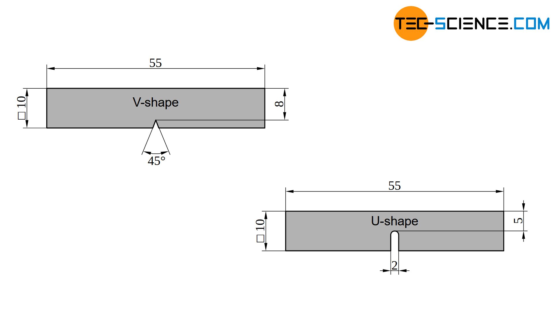
In the Charpy impact test, a notched specimen is abruptly subjected to bending stress. The specimen is usually 55 mm long and has a square cross-section with an edge length of 10 mm. The notch in the middle has a V-shaped geometry (in special cases also U-shaped). The notch provides a defined predetermined breaking point, which generates a triaxial stress state in the notch base. The notched specimen is placed into the support of a pendulum impact testing machine.
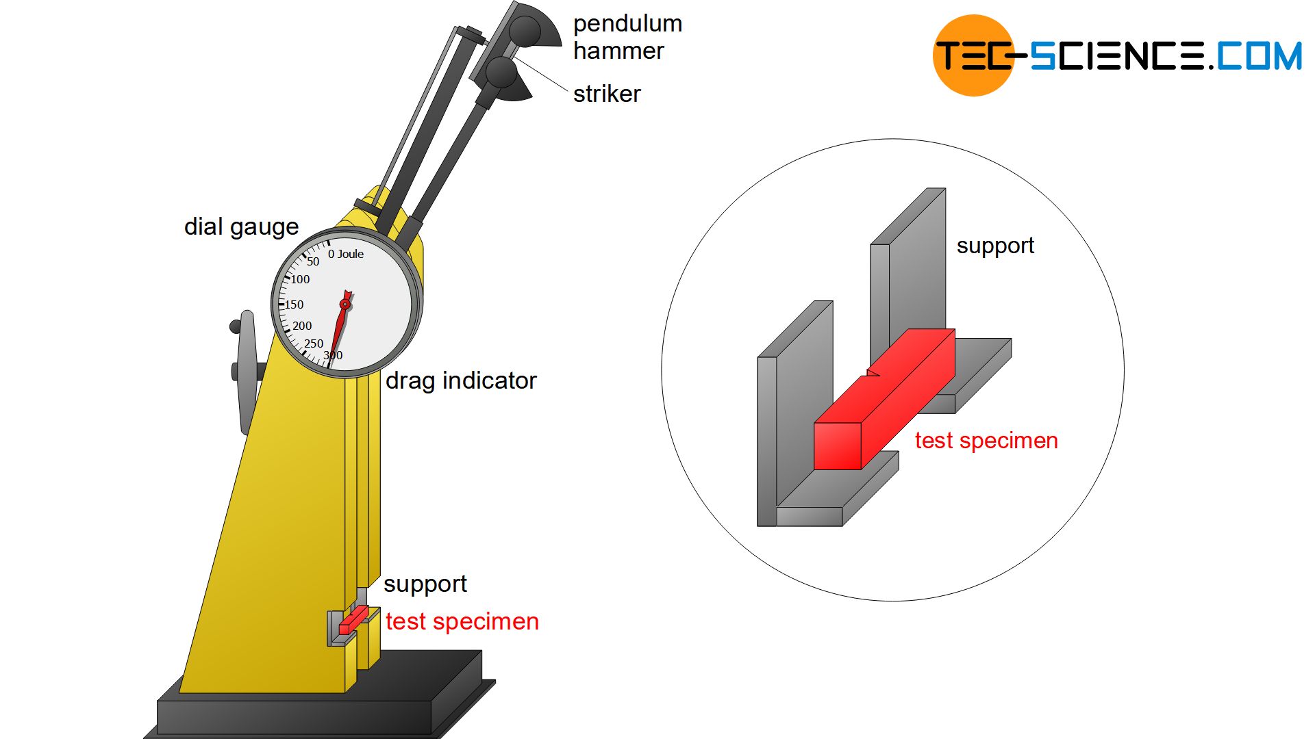
A deflected pendulum hammer is then released from a certain height. At the lowest point of the circular trajectory, the striker of the hammer hits the opposite notch-facing side of the specimen (impact velocity usually between 5.0 and 5.5 m/s). The sample is fractured by the striker and absorbs part of the kinetic energy of the hammer. With the remaining residual energy, the hammer swings out to a certain height. Due to the absorbed kinetic energy through the sample, however, it does not reach its initial height again.
The deformation energy and thus the final height achieved depends on the toughness of the specimen. The tougher the material, the more it has to be deformed until it breaks. The required deformation energies are correspondingly high and the pendulum energy is strongly absorbed. The hammer then only reaches a low final height after fracturing the specimen.
Very brittle specimens, on the other hand, break almost without deformation and therefore require only a low deformation energy. The pendulum hammer swings almost at the initial level. Such a comparison between a tough and brittle fracture behavior is only possible if identical specimen geometries are used.
The deformation energy required for fracturing the specimen is called notch impact energy \(K\) (\(KV\): specimens with V-notch; \(KU\): specimens with U-notch). The notch impact energy can therefore be determined from the difference between the potential energy of the pendulum hammer at the beginning \(W_b\) and the potential energy at the end \(W_e\).
The notch impact energy indicates the energy required to fracture a specimen and is therefore a measure of the toughness of a test specimen! Tough samples have higher notch impact energy values than brittle samples!
At a given initial height \(H\) and mass \(m\) of the pendulum hammer, the notch impact energy depends only on the final height \(h\). The notch impact energy can be read off directly from a dial gauge by a drag indicator, which is carried along from the lowest point as soon as the pendulum hammer hits the specimen.
\begin{align}
\label{kerbschlagarbeit}
&K = W_b – W_e = m \cdot g \cdot H – m \cdot g \cdot h = m \cdot g \cdot \left(H-h \right) \\[5px]
&\boxed{K = m \cdot g \cdot \left(H-h \right)} ~~~~~[K_V]=\text{J} ~~~~~\text{notch impact energie} \\[5px]
\end{align}
Abbildung: Kerbschlagproben
The notch impact energy determined in this way strongly depends on the cross-sectional area of the specimen. Large cross-sections always require higher deformation energies than smaller ones, even if under certain circumstances a more brittle behavior is present. Comparisons in toughness by the notch impact energies are therefore only possible if they were obtained from identical specimen geometries. If at all, a comparison with different geometries is only possible if the notch impact energy \(K\) is related to the cross-section \(A_K\) of the specimen. This quotient of notch impact energy and cross-sectional area is often referred to as notch toughness \(\alpha\), although in most cases this term is used identically to that of notch impact energy..
\begin{align}
\label{kerbschlagzaehigkeit}
&\boxed{\alpha = \frac{K}{A_K}} ~~~~~[\alpha]=\frac{\text{J}}{\text{mm²}} ~~~~~\text{notch toughness} \\[5px]
\end{align}
Note that even notch toughness \(\alpha\) is not a pure material parameter, as it is not dependent on the material alone. The notch impact energy and thus the notch toughness is also influenced by the shape of the specimen cross-section and in particular by the shape of the notch and the speed at which the hammer hits the specimen (more on this in the section on fracture types). Thus, notch impact energy and notch toughness are purely technological parameters that are not included in any dimensioning calculations.
Notch impact energy values are technology parameters and can only be compared with each other if they were obtained from identical specimen geometries with identical boundary conditions (e.g. impact speed, temperature, notch shape, etc.)!
Upper shelf, lower shelf and transition temperature
However, the mentioned influences on notch impact energy, such as fracture speed, temperature and notch shape, are only of minor significance with regard to the actual objective of the Charpy impact test. This is because the V-notch test serves less to compare different materials with each other than to qualitatively compare the toughness of a single material at different temperatures!
In this way, it is possible, for example, to determine at what temperature a material becomes brittle in order to specify the limits of use of the material. For this purpose, the Charpy impact test must only be carried out sufficiently often on samples of the same material at different temperatures. If this is done in this way, especially materials with a body-centered cubic lattice structure (bcc) such as ferritic steels and materials with hexagonal lattice structures (hex) show a particularly strong dependence of toughness on temperature.
While these materials have high toughness at high temperatures, they become brittle at low temperatures. Many plastics show such a behaviour as well, which also begin to become brittle at low temperatures, while they are relatively tough at high temperatures. This behaviour can be illustrated graphically by plotting the notch impact energy as a function of the temperature.
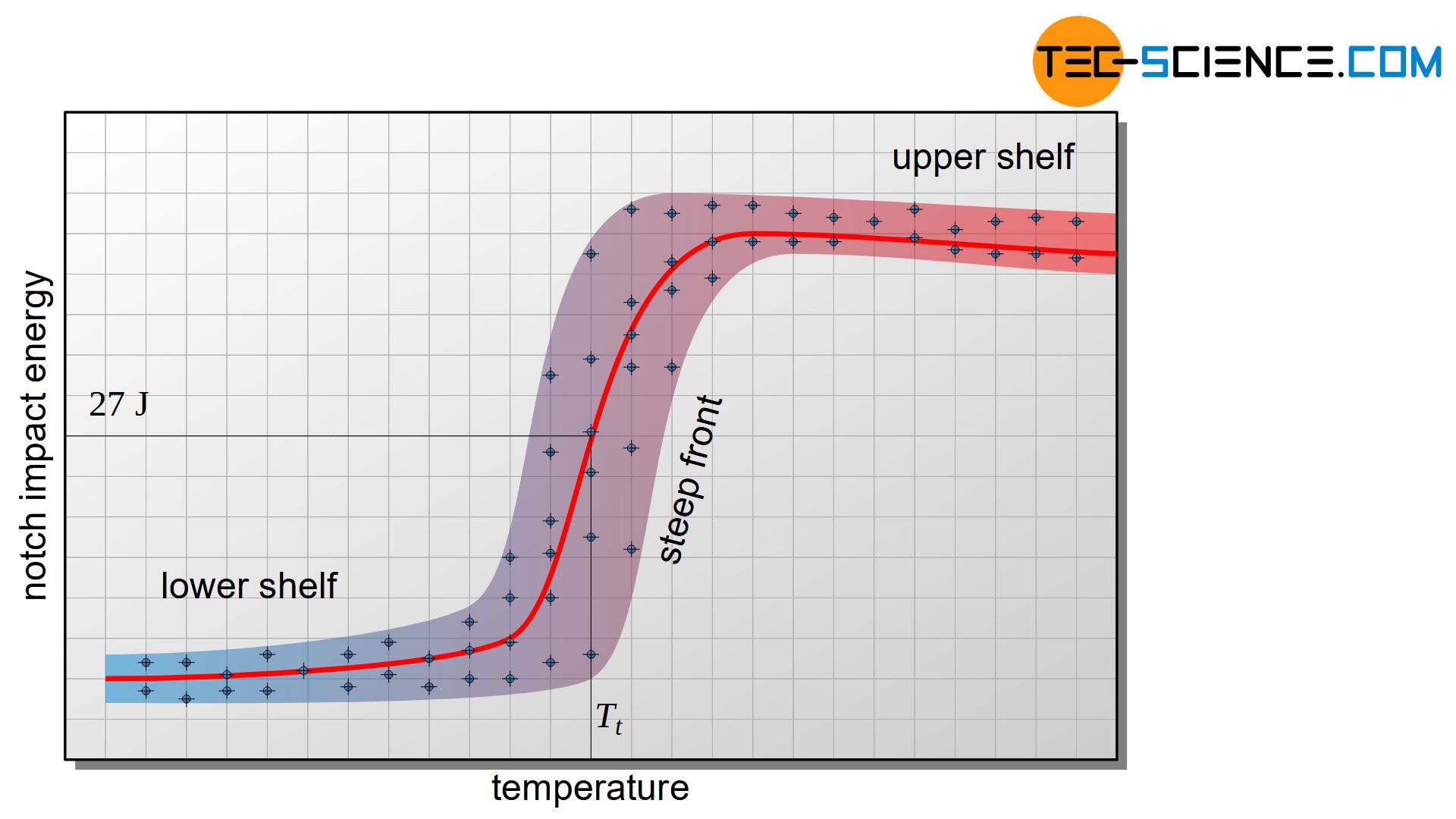
In body-centered cubic and hexagonal lattice structures, the notch impact energy values are very strongly dependent on temperature! For such materials, the brittleness behavior is therefore strongly influenced by temperature!
The temperature range at which the specimen has low notch impact energy values and thus behaves brittle is referred to as lower shelf. Accordingly, the upper shelf indicates the temperature range at which the material behaves relatively tough. Between the lower and the upper shelf there is a transition range, which is characterized by strongly scattering values.
The reason for the large scattering in the transition area lies in small microstructural differences between the individual samples, which cause the material to become brittle at slightly higher or lower temperatures. Therefore, the toughness scatters very strongly despite identical temperatures. Due to the steeply sloping curve from upper shelf to lower shelf, this transition range is also referred to as steep front.
Due to the continuous curve from the upper to the lower shelf, no specific temperature can be assigned to this transition. Nevertheless, different approaches are used to define such a transition temperature in order to identify the temperature below which embrittlement of the material is to be expected.
The transition temperature is frequently defined by the notch impact energy itself. The transition temperature \(T_t\) is often defined as the temperature at which the specimen has an average notch impact energy of 27 J (\(T_{t,27J}\)). However, values of 40 J or 60 J can also be used to define the transition temperature (\(T_{t,40J}\) or \(T_{t,60J}\)). It is also possible to define the transition temperature as the temperature at which the notch impact energy corresponds to 50 % of the upper shelf.
The transition temperature is the temperature below which a material sample shows a rather brittle behaviour in the Charpy impact test and above the transition temperature a rather tough one!
In comparison to materials with body-centered cubic lattice structures, the temperature has hardly any influence on the toughness for materials with face-centered cubic lattice structures such as aluminium. With such materials there is no pronounced lower or upper shelf and therefore no steep front! Some materials behave relatively tough over the entire temperature range, such as aluminium, or show relatively brittle behaviour, such as hardened steels (not tempered) or lamellar graphite castings.
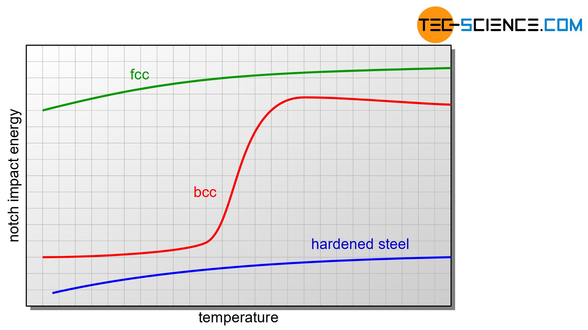
Materials with face-centered cubic lattice structures generally do not show a pronounced upper or lower shelf; they behave either brittle or tough over a wide temperature range!
Testing of state structure
Toughness is not only influenced by temperature but also by the structural state of the material. Quenched and tempered steels and fine-grained structural steels, for example, are characterised by their special toughness. Compared to normalized steels, this remains unchanged even at lower temperatures. The steep front in quenched and tempered steels therefore shifts to lower temperatures. In this way, the Charpy impact test can also be used to check heat treatments or structural conditions.
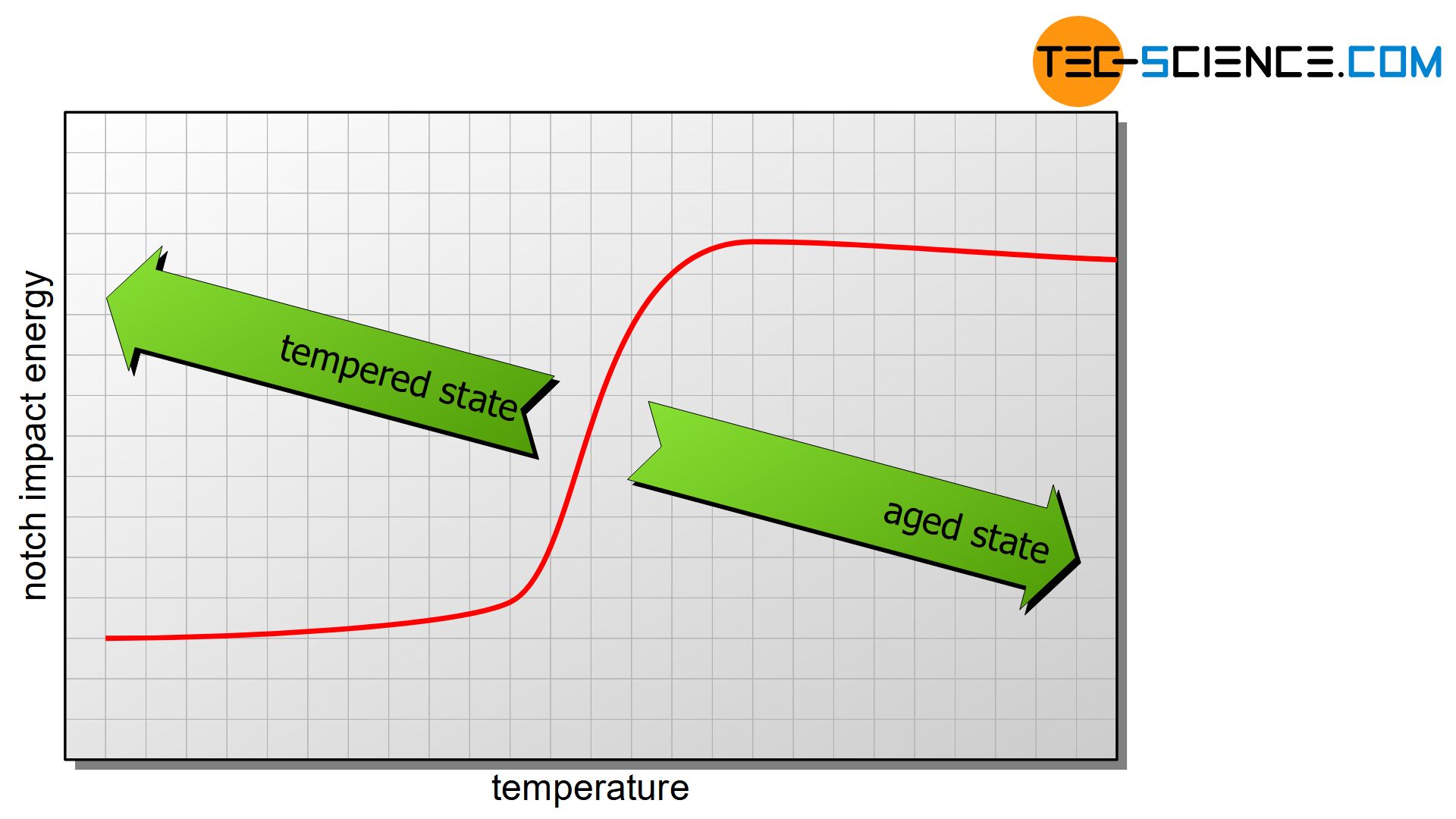
The reverse effect on the position of the steep front in steels is caused by aging. Aging leads to embrittlement and consequently shift the transition temperature to higher values. Thus, the influence of aging effects can also be examined in the Charpy impact test. Hardened steels also show a shift in transition temperature to higher values due to their low toughness.
The Charpy impact test can also be used to check state structures (heat treatment, aging, etc.)!
In summary, the Charpy impact test may have the following objectives:
- Determination of the transition temperature (onset of possible embrittlement)
- Verification of heat treatments
- Examination of aging effects
Indication of notch impact energy values
In addition to the notch impact energy value, the indication of the test result shall also include the notch shape and possibly the energy capacity of the pendulum impact tester (\(W_b\)) . The energy capacity can be omitted if the energy capacity corresponds to the standard value of 300 J. For example, the indication “KV 150 = 40 J” means that the notch impact energy was 40 J in total when using a 150-Joule pendulum impact tester and a V-shaped notched specimen. If the notch impact energy had been obtained on a specimen with a U-shaped notch and a standard pendulum impact tester of 300 J, the indication would have been: “KU = 40 J”.
Fracture types
The fracture behaviour of the specimens used cannot only be assessed on the basis of the notch impact energy. Even the form of the fracture provides information about the toughness or embrittlement of the specimen.
A very tough behaviour can be seen by a strongly deformed fracture surface. Often the ductile sample is not even divided into two parts but only pulled through the two supports in a strongly deformed state. Such a fracture on the upper shelf is therefore also called a deformation fracture or sliding fracture. The fracture surface of steels appears in a matt grey. Under the microscope, the fracture surface shows a honeycomb-like structure.
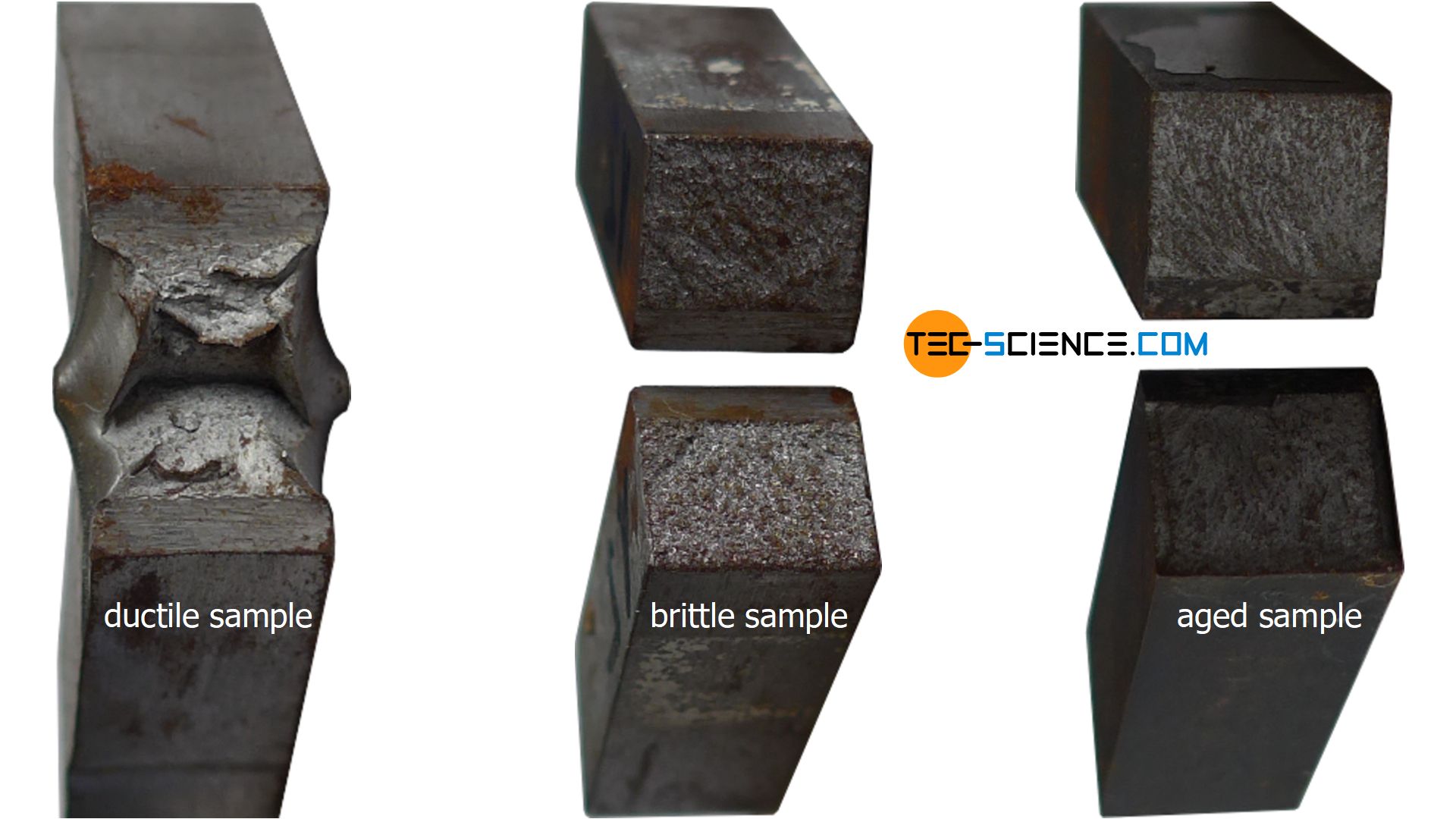
Deformation fracture (sliding fracture) is the fracture of a tough specimen in which the fracture surface shows very strong deformation (high notch impact energy values)!
On the lower shelf, however, there is hardly any deformation. The sample is usually separated in two halves when the hammer strikes. Such brittle fracture is also referred to as cleavage fracture. The fracture surface appears shiny whitish. In the transition temperature range, the fracture surface often shows characteristics of both types of fracture, i.e. a strongly deformed area followed by an area with less deformation. This type of fracture is then also referred to as mixed fracture.
Brittle fracture (cleavage fracture) is the fracture of a brittle specimen in which the fracture surface shows only slight deformation (low notch impact energy values)!
Influence of impact speed on notch impact energy
As far as impact load and specimen geometry are concerned, the Charpy impact test is carried out under precisely defined conditions. Therefore, the results cannot easily be applied to real situations. The deformation speed (impact speed) also has a major influence on the fracture behaviour. If the pendulum hammer hits the specimen at higher speeds, brittle fracture is favoured and the notch impact energies decrease. Conversely, lower deformation speeds are more likely to lead to a deformation fracture with correspondingly higher notch impact energy values.
Due to high impact speeds, the stress in the material increases so rapidly that the bond strength (cohesion strength) of the atomic planes is exceeded before the dislocations could have moved through the material to a significant extent. Note that dislocations do not move infinitely fast but can only move at the speed of sound! A plastic deformation, which is ultimately based on dislocation movements, therefore does not take place at very high deformation speeds. The material breaks practically without deformation by tearing apart the atomic planes (cleavage fracture). Preference is given to those atomic layers that are relatively loosely packed.
Brittle fracture is favoured by high deformation speeds!
At slow deformation speeds, however, the dislocations can move over long distances and deform the material when the critical shear stress is reached. The material is then plastically deformed before it fractures (deformation fracture).

